


3-39
Cisco MGX 8800/8900 Series Hardware Installation Guide
Releases 2 - 5.2, Part Number OL-4545-01, Rev. H0, May 2006
Chapter 3 Preparing for Installation
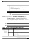
Site Requirements for the MGX 8950 Switch
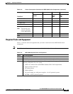
Required Tools and Equipment
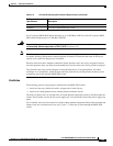
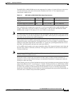
Table 3-14 lists the tools and equipment that you need to install and remove MGX 8950 switch
components.
Note For additional cabling requirements, see Appendix B, “Cable Specifications.”
• MGX-1GE 11
• MGX-2OC12POS-IR 15
• MGX-2GE 13
XM60 55.3
Fan tray (for each)
Note Two fan trays are
needed at all times
for the MGX 8950.
75.6
DC PEM 20
Totals
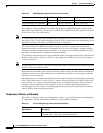
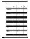
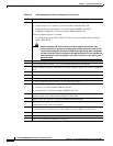
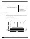
Table 3-13 Power Consumption Calculation for MGX 8950 Switch Components (continued)
Front Card
ABCD
Number of Cards
Installed
Watts Per Card Total Card
Power
(AxB)
Total 48V Current
(ADC)
(C/48)
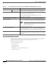
Table 3-14 MGX 8950 Required Tools and Equipment
Check Tools and Equipment
Hardware Components and Cables
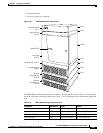
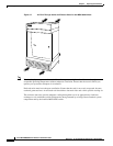
MGX 8950 switch, with the front cards and back cards already installed
If your configuration was not installed in a Cisco-supplied cabinet, you will need the
following components for your system:
• Cabinet or rack that meets the RETMA Standard EIA-310-D requirements
• Upper and lower fan trays
• Air intake plenum
• Exhaust plenum
• AC power supply tray with power supplies—for AC-powered systems
• DC PEM—for DC-powered systems