


5-62
Cisco MGX 8800/8900 Series Hardware Installation Guide
Releases 2 - 5.2, Part Number OL-4545-01, Rev. H0, May 2006
Chapter 5 Installing the Cisco MGX Switch or Gateway
Installing the MGX 8950 Switch
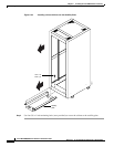
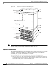
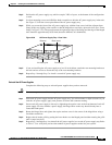
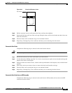
Figure 5-38 Removing an AC Power Supply
Step 3 Tilt the air intake grille down to about a 45-degree angle, lift it out, and set it aside. This exposes the
hinged door that serves as the power supply retainer bracket.
Step 4 With a flat-blade screwdriver, unscrew the captive retainer screw in the center of the hinged door and tilt
the door down.
Step 5 Loosen the captive screw at the bottom front of the AC power supply that you want to remove.
Step 6 Grip the handle and carefully remove the AC power supply by pulling it toward you.
Step 7 Repeat Step 5 and Step 6 for each AC power supply present in each AC power supply tray.
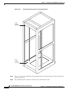
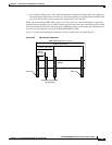
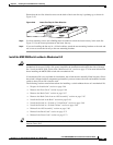
Install the AC Supply Power Tray(s)
Complete the following steps to install the AC power supply tray(s):
Note For optimum performance, it is recommended that you install dual AC power systems for full
redundancy.
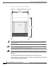
Step 1 Use mounting screws and a Phillips-head screwdriver to attach the mid-mounting brackets to the AC
power supply tray if you are installing the system in a 19-inch or 23-inch rack. Insert each mounting
screw from the inside of the AC power supply tray so that the nut is on the outside of the tray. A mounting
kit is needed for a 23-inch rack (Cisco Part Number MGX-MNT23-8950).
Note If you are installing the AC power supply tray in a 19-inch cabinet, it is front-mounted in the
rack with support from rear brackets.
44142
A
C
D
C
1200W
A
C
D
C
1200W
A
C
D
C
1200W
A
C
D
C
1200W
Released
air intake
grille
Access
hole
Latch
Power
supply