


5-19
Cisco MGX 8800/8900 Series Hardware Installation Guide
Releases 2 - 5.2, Part Number OL-4545-01, Rev. H0, May 2006
Chapter 5 Installing the Cisco MGX Switch or Gateway
Installing the MGX 8850 (PXM1E/PXM45) Switch, MGX 8850/B or MGX 8880 Media Gateway
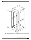
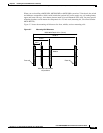
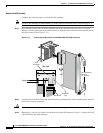
Step 2 Position the AC power supply tray, which occupies 3 RUs of space, at the bottom of the configuration
or rack.
Step 3 Use four mounting screws and a Phillips-head screwdriver to bolt the AC power supply tray in the rack.
See Figure 5-5 for the correct placement of the AC power supply tray.
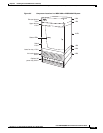
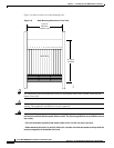
Step 4 While you secure the front of the AC power supply tray with the front screw, hold the adjacent front
flange of the tray slightly to the outside so that the hinged door can freely open and close. (See “Front
flange” in Figure 5-10.) The space between the right-angle edge of the flange and the edge of the hinged
door should be approximately 0.030 inch (about the thickness of a thumbnail).
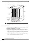
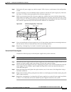
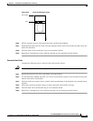
Figure 5-10 AC Power Supply Tray—Front View
Step 5
If you are installing the AC power supply tray in a 19-inch cabinet, attach the rear-mounting brackets to
the rack and use screws to secure the tray to the rear-mounting brackets.
Step 6 Repeat Step 1 through Step 5 to install a second AC power supply tray.
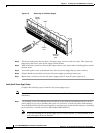
Reinstall the AC Power Supplies
Complete the following steps to reinstall power supplies that you have removed.
Caution Do not use a power screwdriver on captive screws.
Step 1 Slide each AC power supply into the AC power supply tray. You will encounter a slight resistance as you
slide the AC power supply; apply even pressure to ensure full connector mating.
Step 2 Secure each AC power supply to the tray by tightening the captive screw at the front bottom of each AC
power supply. For slots without a power supply, the hinged door on the tray should already have a
removable blank panel.
Step 3 Rotate the hinged door and tighten the captive retainer screw in the center of the hinged door using a
flat-blade screwdriver.
Step 4 Replace the air intake grille by putting the lower hooks over the hinged panel and then rotating the grille
until it snaps into place.
Step 5 Repeat Step 1 through Step 4 to reinstall the AC power supplies in a second AC power supply tray. Refer
to Table 1-5 to verify that you have the number of power supplies needed for your system.
17672
1
2
0
0
W
D
C
A
C
1
2
0
0
W
D
C
A
C
1
2
0
0
W
D
C
A
C
1
2
0
0
W
D
C
A
C
Air intake grille Front flange
Blank panelRelease