


3-37
Cisco MGX 8800/8900 Series Hardware Installation Guide
Releases 2 - 5.2, Part Number OL-4545-01, Rev. H0, May 2006
Chapter 3 Preparing for Installation
Site Requirements for the MGX 8950 Switch
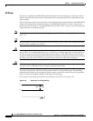
DC Power
DC power is supplied to the MGX 8950 switch through one or two DC PEMs. Each DC PEM must be
connected to a dedicated 100 A regulated source.
Each branch circuit must have a 100 A circuit breaker at the source. Wires connecting the PEMs to the
sources should be capable of carrying 100 A. A 6-AWG (10-square mm) copper wire is recommended.
Consult the local or national codes for conductor sizing for DC supply connections if necessary.
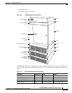
Note For more information about the DC PEM, see the “DC Power Entry Module” section on page 1-30.
DC power sources must be dedicated DC branch circuits. Each branch circuit must be protected by a
dedicated circuit breaker. The circuit breaker must have a rated trip delay time greater than that of the
Cisco MGX 8950 switch circuit breaker.
The MGX 8950 switch uses a 100 A, 1-pole circuit breaker with a short trip delay on each –48 V input.
It is recommended that the site have a dedicated 100 A, 1-pole circuit breaker with a medium trip delay
at each branch circuit.
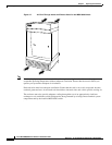
Connect the safety grounding wire to a solid earth ground. It is recommended that you use a ring terminal
lug to terminate the ground conductor at the ground stud. For details, see the “Bonding and Grounding
the Cisco MGX System” section on page C-8.
Caution The –48 VDC return, logical grounds, and safety grounds are connected to the equipment chassis;
therefore, you must use a low-impedance connector to connect the chassis ground to the earthing ground.
Note Connect the MGX 8950 switch only to a –48 VDC source that complies with the SELV requirements in
UL 1950, IEC 950, EN 60950, and CSA C22.2 No. 950-95.
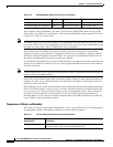
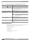
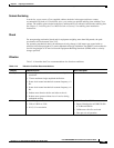
Power Consumption Calculation Tables
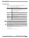
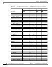
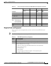
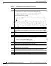
You can use Table 3-13 to calculate the typical power requirement for a MGX 8950 switch.
Table 3-13 Power Consumption Calculation for MGX 8950 Switch Components
Front Card
ABCD
Number of Cards
Installed
Watts Per Card Total Card
Power
(AxB)
Total 48V Current
(ADC)
(C/48)
AXSM-1-2488/B 85.8
• SMFLR-1-2488/B 19.4
• SMFSR-1-2488/B 19.4
• SMFXLR-1-2488/B 19.4
AXSM-1-9953-XG 186
• SMFIR-1-9953 24
• SMFLR-1-9953 24
• SMFSR-1-9953 24