


B-9
Cisco MGX 8800/8900 Series Hardware Installation Guide
Releases 2 - 5.2, Part Number OL-4545-01, Rev. H0, May 2006
Appendix
External Alarm Cabling
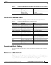
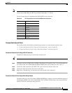
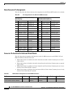
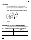
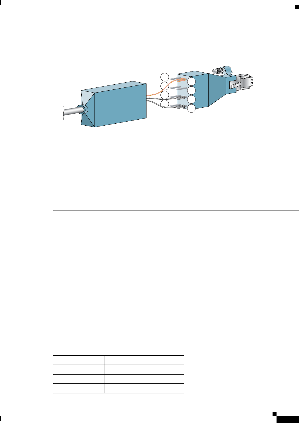
Step 3 Use a wire-wrapping tool to wrap the shield drain wire to the ground pin (pin 3 or 6) of the adapter. The
shield drain wire is the bare wire shown in Figure B-5.
Figure B-5 Wires Wire-Wrapped to Pins
Step 4 Use a wire-wrapping tool to wrap the two remaining wires to the pin of the adapter.
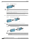
Step 5 Slide the pin cover over the pins and onto the body of the adapter after all of the wires are connected.
Step 6 Insert the RJ-45 connector of the adapter into the EXT CLK1 or EXT CLK2 port on the PXM-UI-S3 or
PXM-UI-S3/B.
Step 7 If the faceplate of the PXM-UI-S3 or PXM-UI-S3/B has a mating tapped hole, hand tighten the
strain-relief screw to provide additional strain relief.
Step 8 Connect the opposite end of the shielded cable to the external BITS clock source.
External Alarm Cabling
The network alarm cable connects to the ALARM connector on the PXM-UI-S3 or PXM-UI-S3/B user
interface card.
Alarm Cable Information
This section describes cables, connectors, and pin assignments for network alarm cabling.
Alarm Cable Information for MGX Switches
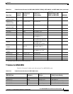
Table B-7 describes the Alarm cable used for the MGX 8850 (PXM1E/PXM45), MGX 8850/B,
MGX 8950, MGX 8830 and MGX 8830/B switches.
5
6
7
8
53281
1
2
3
4
Table B-7 External Alarm Cable and Connector Information for MGX Switches
Cable Parameter Description
Interface Dry-contact relay closure
Wire 24 AWG, shielded, 6-pair
Connector DB-15, subminiature, male