


5-104
Cisco MGX 8800/8900 Series Hardware Installation Guide
Releases 2 - 5.2, Part Number OL-4545-01, Rev. H0, May 2006
Chapter 5 Installing the Cisco MGX Switch or Gateway
Installing the MGX 8830 or MGX 8830/B Switch
Ground the Frame Bonding Ground Connection for a Cisco-Supplied Rack
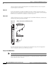
A Cisco-supplied rack has two pairs of grounding studs located at the top and bottom of the rack. The
rack comes with the hardware needed to secure a ground conductor to the grounding studs. The
grounding studs measure 1/4 inch by 20 threads per inch. The grounding studs can accept a two-holed
grounding connector designed to prevent rotation and possible loosening of the connector.
Note If you are installing your switch in a third-party vendor rack or cabinet, ensure that the rack and cabinet
are properly grounded.
Caution The chassis ground wire must be the same size as the return conductor so that it can carry the entire
battery load. See the “Wiring a Mixed Ground System with Redundant Supplies” section on page C-9
for more information.
Caution When moving a Cisco-supplied cabinet, do not push the cabinet at its sides. Instead, grip the front or
back edges of the cabinet.
The ground conductor is typically connected to the building earth wiring, usually at a power distribution
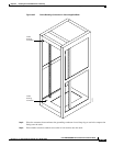
board. Complete the following steps to attach a ground conductor to the frame of a Cisco rack:
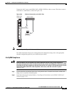
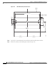
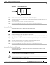
Step 1 Place the external, toothed star washers onto a stud. Figure 5-67 shows a Cisco cabinet with the frame
bonding connection studs in the upper and lower parts of the cabinet. Only one of the studs is needed to
make the connection. A ground symbol on the Cisco rack indicates the points of attachment.