


C-11
Cisco MGX 8800/8900 Series Hardware Installation Guide
Releases 2 - 5.2, Part Number OL-4545-01, Rev. H0, May 2006
Appendix
Bonding and Grounding the Cisco MGX System
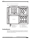
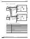
As Figure C-2 shows, the non-isolated system has a 48-VDC return that internally connects to the
backplane. (This design calls for a hard-wired return and so does not allow for an optional or alternate
ground connection.) The internal connection provides a low-impedance connection between 48-VDC
return and frame ground. This grounding scheme protects the signals on the backplane from corruption
by transients that can result from lightning or electrostatic discharge.
To improve protection against transients, the loop area (and resultant loop impedance) should be made
as small as possible by locating the –48-VDC supply, 48-VDC return, and protective earth conductors
as close to each other as possible.
As recommended in ITU-T K.27, the multipoint grounding in a mesh bonding network provides the best
protection for equipment by providing the lowest impedance in the ground system. For more detailed
information, refer to the recommendation itself.
Conductor Characteristics for Carrying Current and Ensuring Low Voltage
Drops
For signal degradation to be averted, a conductor must be large enough to prevent its impedance from
creating a voltage drop equal to 2 percent of the reference voltage. Also, the protective earth conductor
must be large enough to carry all the current if the 48 VDC return fails. This latter requirement is for
safety. Full fault redundancy is achieved by having equal size conductors for the protective earth ground
and the 48 VDC return of the switch.
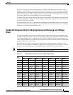
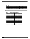
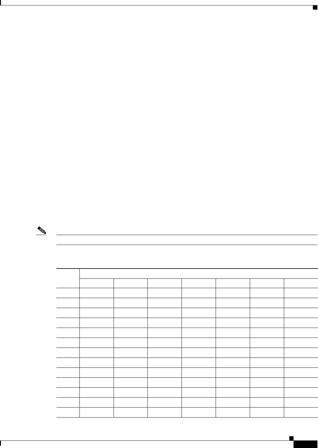
For wire gauges that prevent unacceptable voltage drops over different lengths of copper wire, see
Table C-2. For the resistance of 1000 feet of copper wire for each gauge of wire, see Table C-3. These
references are for planning purposes and might be further subject to local laws and practices.
Note Table C-2 is for reference. It is recommended that you use 50-A or greater.
Table C-2 Wire Gauge for Current Loads over Copper Wire Lengths
DC
Current
Distance in Feet
25 feet 50 feet 75 feet 100 feet 150 feet 200 feet 400 feet
5 A 18 gauge 14 gauge 14 gauge 12 gauge 10 gauge 8 gauge 6 gauge
10 A 14 gauge 12 gauge 10 gauge 8 gauge 8 gauge 6 gauge 2 gauge
15 A 14 gauge 10 gauge 8 gauge 8 gauge 6 gauge 4 gauge 2 gauge
20 A 12 gauge 8 gauge 8 gauge 6 gauge 4 gauge 2 gauge 0 gauge
25 A 12 gauge 8 gauge 6 gauge 4 gauge 4 gauge 2 gauge 0 gauge
30 A 10 gauge 8 gauge 6 gauge 4 gauge 2 gauge 2 gauge 00 gauge
35 A 10 gauge 6 gauge 4 gauge 2 gauge 2 gauge 1 gauge 000 gauge
40 A 8 gauge 6 gauge 2 gauge 2 gauge 2 gauge 0 gauge 000 gauge
45 A 8 gauge 6 gauge 4 gauge 2 gauge 1 gauge 0 gauge 0000 gauge
50 A 8 gauge 4 gauge 4 gauge 2 gauge 1 gauge 00 gauge —
55 A 8 gauge 4 gauge 2 gauge 2 gauge 0 gauge 00 gauge —
60 A 8 gauge 4 gauge 2 gauge 2 gauge 0 gauge 00 gauge —
65 A 6 gauge 4 gauge 2 gauge 1 gauge 0 gauge 000 gauge —