


4-14
Cisco MGX 8800/8900 Series Hardware Installation Guide
Releases 2 - 5.2, Part Number OL-4545-01, Rev. H0, May 2006
Chapter 4 Planning for Card Redundancy, Line Redundancy, and Bulk Distribution
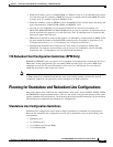
Planning for Standalone and Redundant Line Configurations
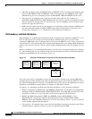
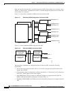
1:N Redundant Card Configurations (Except RPM)
When planning for a standalone line in a 1:N redundant card configuration, consider the following
guidelines:
• A single line (transmit and receive) should be attached to the connectors for each line. Y-cables,
which are introduced earlier for 1:1 redundant card installations, should not be installed.
• For 1:N redundant card configuration without bulk distribution, the redundant card set must be
established according to the guidelines in “1:N Redundancy without Bulk Distribution,” which
appears earlier in this chapter.
• For 1:N redundant card configuration with bulk distribution, the redundant card set must be
established according to the guidelines in “1:N Redundancy with Bulk Distribution,” which appears
earlier in this chapter.
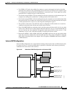
• When bulk distribution is used on the card hosting the standalone line, the line is standalone from
the service module to the SRM card. This is a single physical connection over the switch backplane.
However, when the standalone line reaches the SRM, the SRME and SRME/B can be configured for
redundant lines, if redundant SRMs are used with SONET, SDH, or STM-1 interfaces. When the
SRME or SRME/B is configured for redundant lines, all cards that use bulk distribution through that
card pair have redundant line protection. For more information, see “Redundant Line Configuration
Guidelines,” which appears later in this chapter.
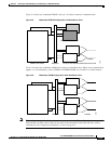
1:N Redundant RPM Configurations
The method you use for connecting multiple RPMs to a single network will depend on the back card
type. For example, if you are configuring two RPM-PRs for 1:N redundant operation over a connection
to a single Ethernet 10/100 network, you would directly connect the corresponding ports or lines to a
hub on that network. You would not use a Y-cable.
For more information on preparing RPM cards for 1:N redundancy, refer to Cisco MGX Route Processor
Module (RPM-PR) Installation and Configuration Guide.
Redundant Line Configuration Guidelines
Redundant line configurations extend fault tolerance to individual lines. As with redundant cards,
redundant lines operate as a pair. If one line fails, the other line in the redundant pair takes over.
Cisco MGX 8850switches use Automatic Protection Switching (APS) to provide line fault tolerance.
APS is a component of SONET and is therefore available only on optical interfaces and STM-1
interfaces (which are the electrical equivalent of SONET OC-3). Table 4-1 lists all the card types and
shows which cards support APS.
Note Redundant lines (APS) are not supported on T1 and E1 cards. However, SRME and SRME/B can
indirectly provide redundant line protection to T1 and to E1 lines when the hosting service modules are
configured for bulk distribution through a redundant SRM card set. For more information, see “Intercard
APS Configurations,” which appears later in this chapter.
The switch installation determines whether the switch can support APS, but APS does not operate until
it is enabled and configured. When planning for APS, the hardware preparation includes:
• Placing front cards in the appropriate slots to support the planned APS configuration.
• Installing an APS connector if required.