


3-28
Cisco MGX 8800/8900 Series Hardware Installation Guide
Releases 2 - 5.2, Part Number OL-4545-01, Rev. H0, May 2006
Chapter 3 Preparing for Installation
Site Requirements for the MGX 8950 Switch
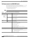
Site Requirements for the MGX 8950 Switch
This section describes requirements for the site where the Cisco MGX 8950 switch is to be installed.
Before you install the switch, ensure that all of the criteria in this section are met.
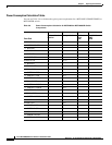
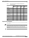
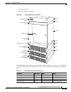
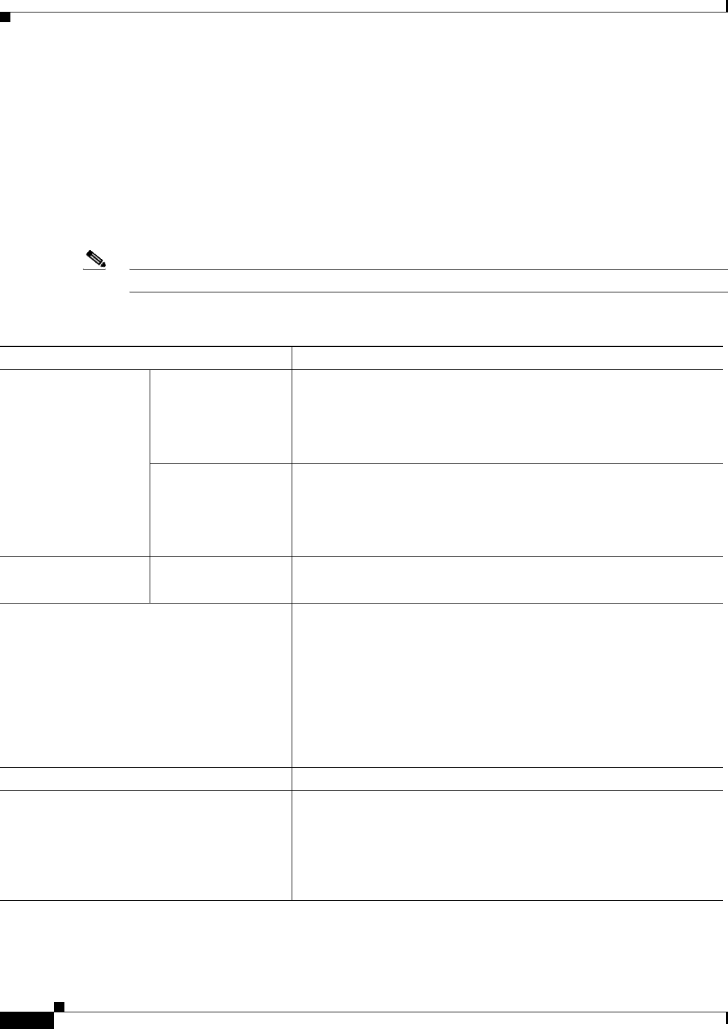
Table 3-8 summarizes the space, weight, and power requirements for the switch. Specifications are
described in greater detail in the following sections:
• Environmental Requirements, page 3-29
• Required Tools and Equipment, page 3-39
Note One rack unit (RU) is equal to 1.75 inches (4.45 cm).
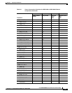
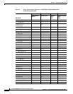
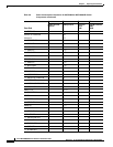
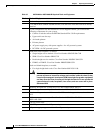
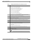
Table 3-8 Space, Weight, and Power Specifications for the MGX 8950 System
Specification Description
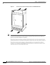
Dimensions
Note Racks must
have 17.75 in.
minimum
between
mounting rails.
DC-powered system 17 RUs
Height: 29.75 in. (75.56 cm)
Width: 19 in. (48.26 cm)
Depth: 21.5 in. (54.6 cm)—Excluding cable management and front door
AC-powered system 20 RUs
Height: 35 in. (88.9 cm)
Width: 19 in. (48.26 cm)
Depth: 21.5 in. (54.6 cm)—Excluding cable management and front door
Weight DC-powered switch
AC-powered switch
Up to 200 lb (90 kg)
Up to 300 lb (136.5 kg)
Shipping weight for individual components Front and back cards: 6.0 lb (2.72 kg) per card set
Card cage with cards: 160 lb (72.64 kg)
Exhaust plenum: 8 lb (3.63 kg)
Fan tray: 9.5 lb (4.3 kg)
Air intake plenum: 8 lb (3.63 kg)
AC power supply tray with power supplies: 45 lb (20.43 kg)
APS connector: 1 lb (0.45 kg)
Clearance requirement for the enclosure Minimum 30 in. front and rear; 12 in. side clearance recommended
Power input voltage
• AC source: Normal operating range is 200 to 240 VAC, 47 to 63 Hz.
The maximum voltage range is 180 to 254 VAC.
Note The AC power source must be within 6 feet (1.8 meters) of the
system and easily accessible.
• DC source: –42 to –56 VDC.