


4-12
Cisco MGX 8800/8900 Series Hardware Installation Guide
Releases 2 - 5.2, Part Number OL-4545-01, Rev. H0, May 2006
Chapter 4 Planning for Card Redundancy, Line Redundancy, and Bulk Distribution
Planning for Standalone and Redundant Line Configurations
Standalone Card Configurations
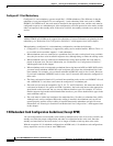
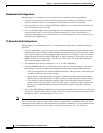
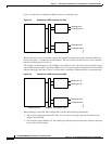
When planning for a standalone line on a standalone card, consider the following guidelines:
• A single line (transmit and receive) should be attached to the connectors for each line. Y-cables,
which are introduced later for 1:1 redundant card installations, should not be installed.
• If the standalone line is for a standalone PXM1E or SRM card, no card should be installed in the
reserved redundant slot for that card.
• Slot 4 on the MGX 8880 switch is preconfigured to use redundant back cards, which physically
connect the front card in slot 4 to any back cards installed in slot 3. Slot 4 cannot support a
standalone configurations on its own. Therefore, it is recommended that you use slot 4 only for 1:1
redundant card configurations.
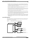
1:1 Redundant Card Configurations
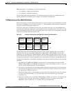
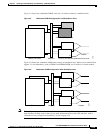
When planning for a standalone line and a 1:1 redundant card configuration, consider the following
guidelines:
• For most installations, a pair of Y-cables must be installed between matching line numbers on the
redundant back cards, one for the transmit connector and one for the receive connector. Each Y-cable
links a pair of transmit or receive connectors to the standalone line. Typically, a pair of Y-cables is
required for each line that uses BNC, SMB, MCC or optical connectors. Some cards, such as the
AXSM-32-T1E1-E, use special back card connectors and Y-cables that route both transmit and
receive paths through a single cable.
• The redundant cards must be configured for 1:1 or “Y-cable” redundancy.
• Y-cabling of MMF backcards is possible, but must be subject to careful evaluation of the optical
power budget. You must consider the following information when Y-cabling MMF interfaces:
–
The losses introduced by the Y-cable assemblies themselves, fiber connectors, patch panels, and
so forth, can affect the optical power budget.
–
Single ended Y-cable deployments are typically within the acceptable optical power budget.
Double ended Y-cable deployments are likely to have too much attenuation to work correctly.
–
Cisco optical Y-cables incorporate an optical splitter, which effectively divides the optical
power in half to each leg of the Y-cable. This split results is an effective 3db attenuation, and
this does not include the additional attenuation introduced by the Y-cable fiber connectors
themselves.
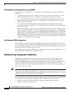
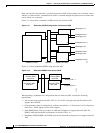
• Slot 4 in the MGX 8880 uses redundancy back cards that connect the front card in slot 4 to any back
cards in slot 3. Because there is only one back card set, no Y-cables are required for standalone line
installations with 1:1 card redundancy in slots 3 and 4.
Note The 1:1 card redundancy configuration is sometimes referred to by the older term, Y-cable redundancy.
This is because older card sets always used Y cables to connect both 1:1 redundant cards to the same
communications line. However, with the addition of the APS line redundancy, it is very common to have
1:1 redundant cards that do not use Y cables, so this guide uses the term 1:1 card redundancy.