


5-53
Cisco MGX 8800/8900 Series Hardware Installation Guide
Releases 2 - 5.2, Part Number OL-4545-01, Rev. H0, May 2006
Chapter 5 Installing the Cisco MGX Switch or Gateway
Installing the MGX 8950 Switch
Note These instructions are specific to a Cisco-supplied cabinet, but can be used for anchoring a
Cisco-supplied rack. If you are not installing your system in a Cisco-supplied rack or cabinet, anchor
your third-party rack or vendor cabinet according to guidelines in the third-party vendor documentation.
The slots in the stability plate use up to 5/8-inch anchor bolts.
Caution When moving a Cisco-supplied cabinet, do not push the cabinet at its sides. Instead, grip the front or
back edges of the cabinet.
Complete the following steps to anchor your Cisco cabinet to a stability plate:
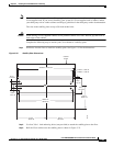
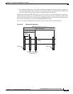
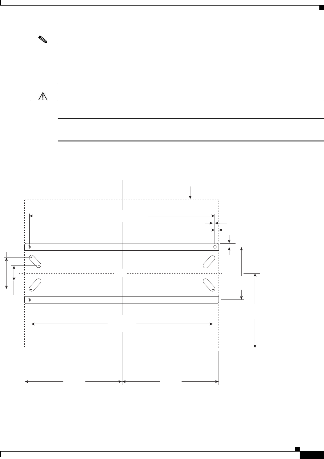
Step 1 Drill holes into the floor to install the stability plate. See Figure 5-32 for the dimensions.
Figure 5-32 Stability Plate Dimensions
Step 2
Use four 3/8 x 1 inch anchoring bolts (user-provided) to attach the stability plate to the floor.
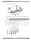
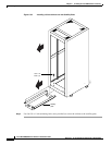
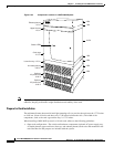
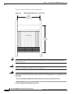
Step 3 Roll the Cisco cabinet over the stability plate as shown in Figure 5-33.
H8380
C
L
3.35 in.,
8.51 cm
6.7 in.,
17.02 cm
3.35 in.,
8.51 cm
Cabinet
outline
9.5 in.,
24.13 cm
0.663 in., 1.68 cm
0.337 in., 0.85 cm
11.55 in.,
29.34 cm
18.0 in.,
45.72 cm
33.875 in.,
86.04 cm
34.550 in., 87.76 cm
18.0 in.,
45.72 cm