


1-13
Cisco MGX 8800/8900 Series Hardware Installation Guide
Releases 2 - 5.2, Part Number OL-4545-01, Rev. H0, May 2006
Chapter 1 Product Overviews
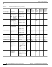
Overview of Card Slot Assignments, by Chassis
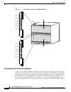
PXM1E-COMBO
7
Processor Switch
Module
4-port OC-3, 8-port
T3/E3
PXM-UI-S3/B Upper 1 and 2 7 and 8 — —
MGX-T3E3-155
Transceivers:
• MMF-1-155-SFP
• SMFLR-1-155-SF
P
• SMFIR-1-155-SFP
Lower
PXM45
7
Processor Switch
Module
UI Stratum-3 Upper — 7 and 8 — —
PXM Hard Disk
Drive
Lower
PXM45/B
7
Processor Switch
Module
UI Stratum-3 Upper — 7 and 8 — 7 and 8
PXM Hard Disk
Drive
Lower
PXM45/C
7
Processor Switch
Module
UI Stratum-3/B Upper — 7 and 8 7 and 8 7 and 8
PXM Hard Disk
Drive
Lower
RPM-PR-256
7
RPM-PR-512
7
Route Processor
Module
MGX-RJ45-4E/B
MGX-RJ45-FE
MGX-MMF-FE
MGX-RPM-1FE-CP
MGX-RJ45-5-ETH
Upper and
lower
3-6 1-6, 9-14 1-6, 9-14 1-6, 11-16
RPM-XF-512
7,13
Route Processor
Module
Lower Bay:
• MGX-XF-UI
Upper Bay:
• MGX-1OC12POS-
IR
• MGX-2OC12POS-
IR
• MGX-1GE
• MGX-2GE
Note Back cards
are optional
with the
RPM-XF.
According
to back
card type
3-6 1-6, 9-14 1-6
permitted,
9-14
preferred
1-6, 11-16
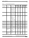
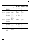
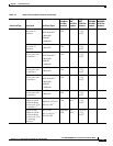
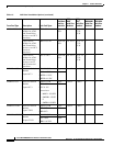
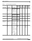
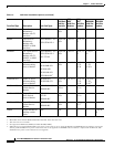
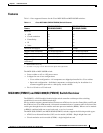
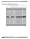
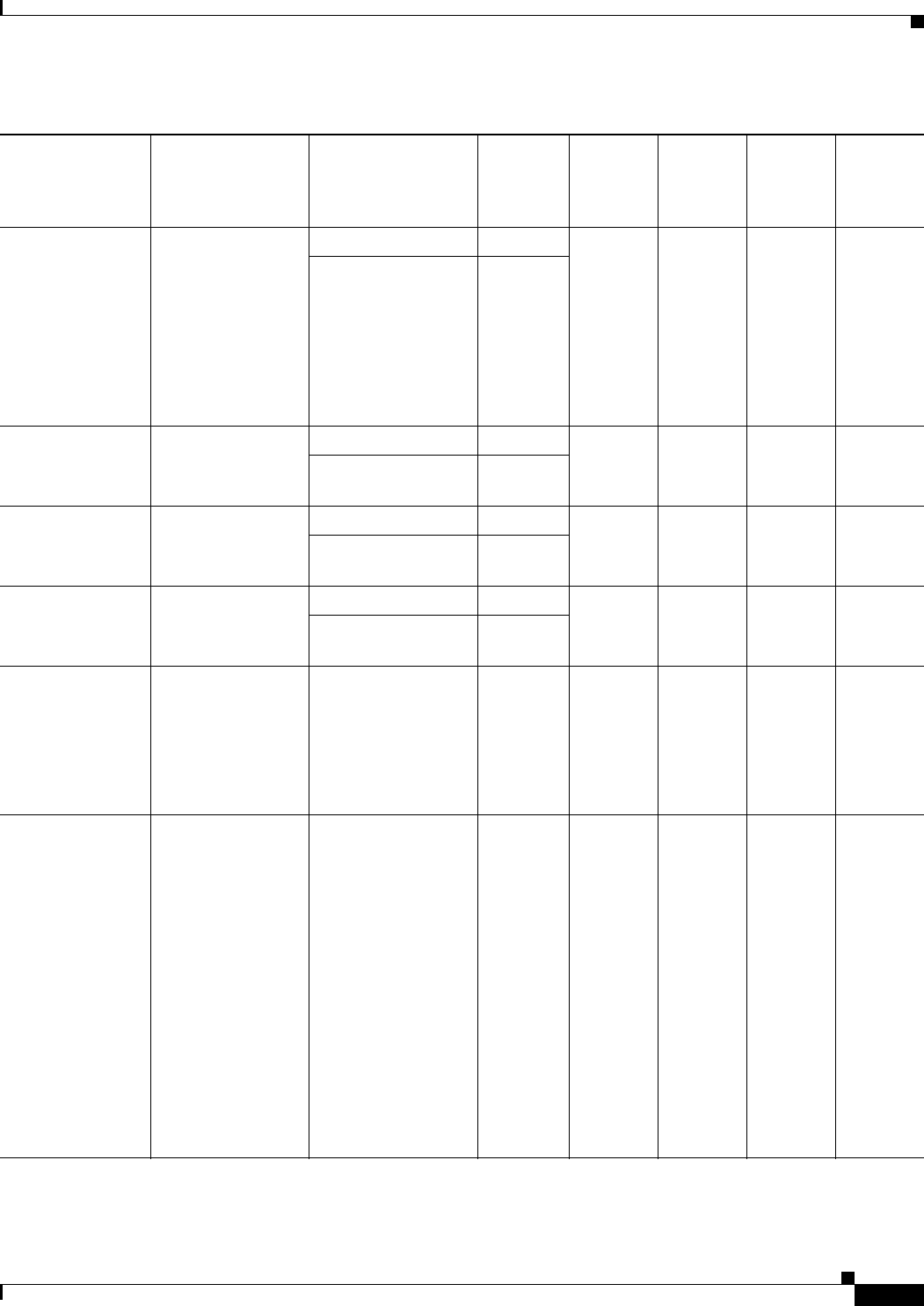
Table 1-3 Valid Card Installation Options (continued)
Front Card Type Description Back Card Types
Valid Back
Card Bay
Locations
MGX
8830
1
Valid Slot
Numbers
MGX
8850
2
Valid Slot
Numbers
MGX 8880
Valid Slot
Numbers
MGX 8950
Valid Slot
Numbers