


5-71
Cisco MGX 8800/8900 Series Hardware Installation Guide
Releases 2 - 5.2, Part Number OL-4545-01, Rev. H0, May 2006
Chapter 5 Installing the Cisco MGX Switch or Gateway
Installing the MGX 8950 Switch
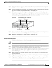
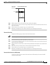
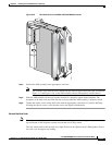
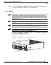
Figure 5-43 Two Back Cards in the MGX-APS-CON-8950Connector
Step 4 Position the APS assembly in the appropriate card slots.
Note The extractor levers must be closed (flush with the vertical edge of the back cards, as shown in
Figure 5-13 and Figure 5-14), or the APS assembly cannot slide properly into the chassis.
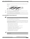
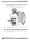
Step 5 Slide the APS assembly all the way into the slot until it is properly seated in the backplane. The
faceplates of the back cards are flush with the card cage when the APS assembly is properly seated.
Step 6 Tighten the captive screws on the back cards with the appropriate screwdriver. If you have difficulty
inserting the captive screws, verify that the screws are aligned with the holes.
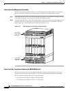
Reinstall the Back Cards
Note All cards must be fully seated in the chassis. When installing the back card, apply even pressure to the
top and bottom of the faceplate to make sure that the card is fully seated.
The card should slide in and out with only slight friction on the adjacent board’s EMI gaskets. Do not
force the card. Investigate any binding.
149631