


1-38
Cisco MGX 8800/8900 Series Hardware Installation Guide
Releases 2 - 5.2, Part Number OL-4545-01, Rev. H0, May 2006
Chapter 1 Product Overviews
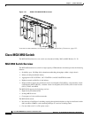
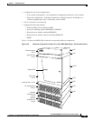
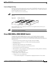
Cisco MGX 8950 Switch
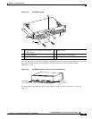
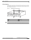
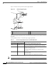
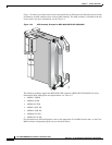
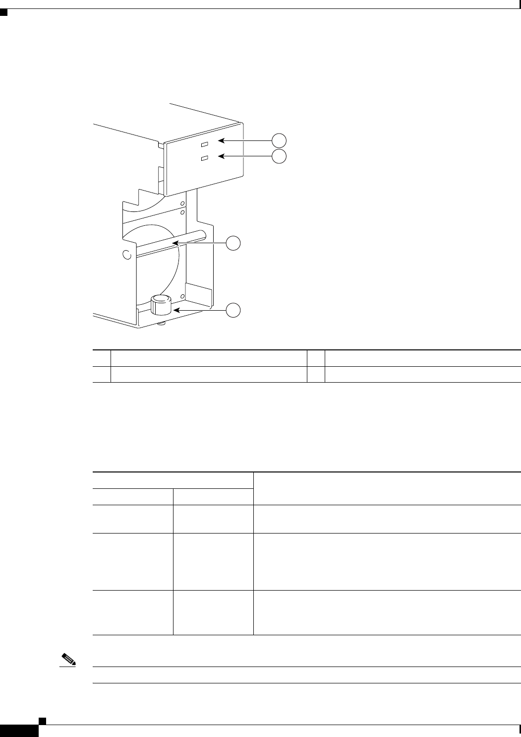
Figure 1-22 shows a close-up of the AC power supply faceplate.
Figure 1-22 AC Power Supply Faceplate
The AC power supply requirements for the switch depend on the number of service modules installed in
the switch.
Use the guidelines in Table 1-7 for the AC power supply requirements.
Note For AC power cord requirements, see the “Required Tools and Equipment” section on page 3-25.
1 DC okay LED—Green 3 Handle
2 AC okay LED—Green 4 Captive screw
A
C
D
C
84458
1200W
1
2
3
4
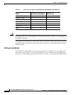
Table 1-7 AC Power Supply Requirements for the MGX 8950 Switch
Number of Service Modules Installed
Number of Power Supplies Required per SwitchDouble-Height Single-Height
1 to 5 1 to 10 4 AC power supplies (2 on each power tray (line cord)) for a
dual, or 2 power supplies in a single AC power cord system.
6 to 10 11 to 20 6 AC power supplies (minimum) for a dual AC power cord
system (3 on each power cord)
3 AC power supplies (minimum) for a single AC power
cord system
11 or more 21 or more 8 AC power supplies (3 on each power cord) for a dual AC
power cord system
4 AC power supplies for a single power cord system