


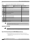

5-5
Cisco MGX 8800/8900 Series Hardware Installation Guide
Releases 2 - 5.2, Part Number OL-4545-01, Rev. H0, May 2006
Chapter 5 Installing the Cisco MGX Switch or Gateway
Installing the MGX 8850 (PXM1E/PXM45) Switch, MGX 8850/B or MGX 8880 Media Gateway
• The current MGX 8850 chassis use a 25-pin connector at the plenum end of the fan tray, but the
MGX 8880 uses a 44-pin connection. The MGX 8880 cable is keyed to ensure it cannot be used on
an MGX 8850 chassis.
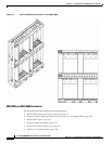
• In the MGX 8880 chassis, color coded slot identification has been added for PXM45 cards and
SRME/B cards. (Cards will have mating color coding—yellow for PXM45; blue for SRME/B.) See
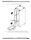
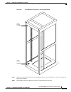
Figure 5-1.
• The MGX 8880 has a guide system for fan tray and power cable insertion.
• Alignment pins have been added to the MGX 8880 back plane to aid with replacing the new
redundancy connector used with the VXSM cards (RCON part is RCON-1TO5-8850). The MGX
8880 comes from the factory with this RCON installed in the top right bay and bottom right bay,
when viewed from the rear of the chassis.
Note The new fan tray for the MGX 8880 replaces two fan trays currently used to cool the MGX 8850 system.
The new fan tray is hot swappable, and for convenience, has a pullout handle.
• The MGX 8880 power supply part numbers are:
–
MGX-PWR-AC-220 (AC power supply - 220 V)
–
MGX-PWR-DC (DC power supply with intake plenum)