


3-41
Cisco MGX 8800/8900 Series Hardware Installation Guide
Releases 2 - 5.2, Part Number OL-4545-01, Rev. H0, May 2006
Chapter 3 Preparing for Installation
Site Requirements for a MGX 8830 or MGX 8830/B Switch
Site Requirements for a MGX 8830 or MGX 8830/B Switch
This section describes requirements for the site where the MGX 8830 or MGX 8830/B switch is to be
installed. Before you install the switch, ensure that all of the criteria in this section are met.
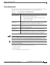
Table 3-15 summarizes the space, weight, and power requirements for the switch. Specifications are
described in greater detail in the following sections:
• Environmental Requirements, page 3-42
• Power Requirements, page 3-47
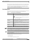
Note One rack unit (RU) is equal to 1.75 inches (4.45 cm).
Caution The AC power source must be within 6 feet (1.8 meters) of the system and easily accessible.
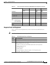
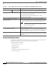
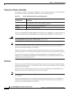
3-in-1 tool (part 700-07569-01) with the following heads:
• A flat head for unlatching front card ejectors and loosening and tightening the back card
captive screws
• A hex head for unlatching the chassis door
• A Phillips head for loosening and tightening the back card captive screws
Power screwdriver, optional
Wire stripper
Wire-wrapping tool, optional
Fuse replacement tool (218090-00).
Warning
This tool should only be used by trained personnel.
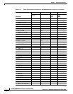
Table 3-14 MGX 8950 Required Tools and Equipment (continued)
Check Tools and Equipment
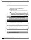
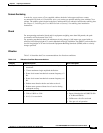
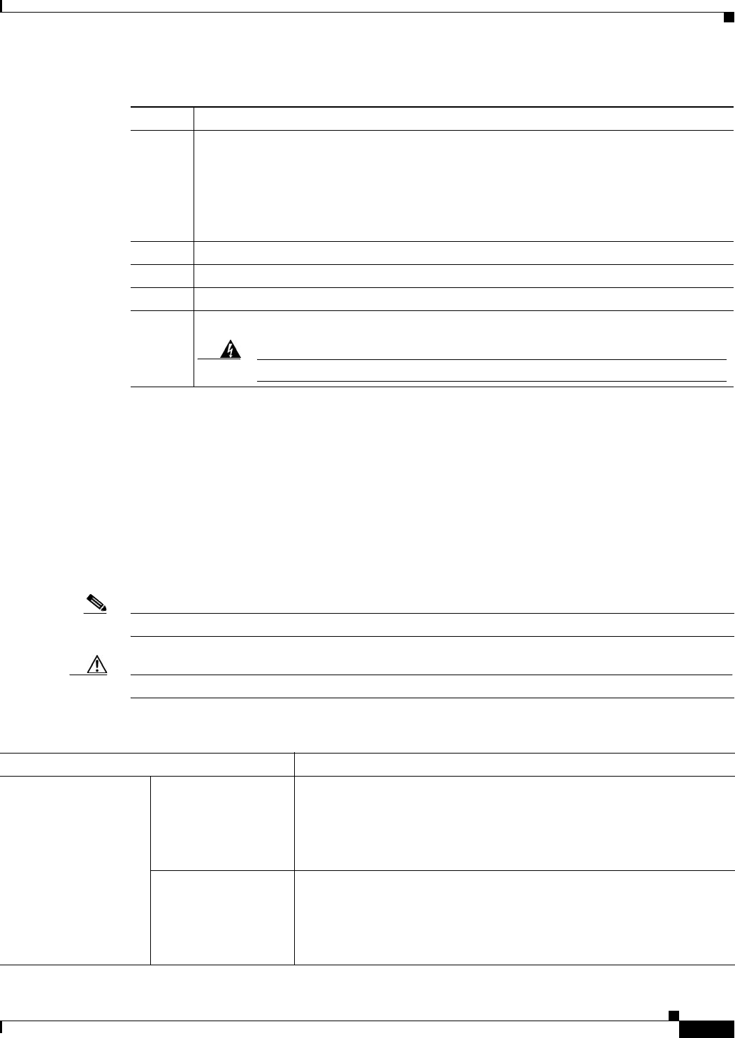
Table 3-15 Space, Weight, and Power Specifications for a MGX 8830 or MGX 8830/B Switch
Specification Description
Dimensions
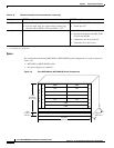
Note Racks must
have at least
17.75 in. (45
cm) between
mounting rails.
DC-powered system 7 RUs
Height: 12.25 in. (31.12 cm)
Width: 17.72 in. (45.01 cm)
Depth: 23.5 in. (59.69 cm)—Excluding cable management and front door
AC-powered system 8 RUs
Height: 14.00 in. (35.56 cm)
Width: 17.72 in. (45.01 cm)
Depth: 23.5 in. (59.69 cm)—Excluding cable management and front door