


6-15
Cisco MGX 8800/8900 Series Hardware Installation Guide
Releases 2 - 5.2, Part Number OL-4545-01, Rev. H0, May 2006
Chapter 6 Maintaining the Cisco MGX Switch or Gateway
Removing the Center Guide Modules
If a center guide module is removed from the rear and one double-height back card is installed, install a
double-height blank faceplate in the gap adjacent to the installed double-height card. Two single-height
blank faceplates cannot be used, because they require being screwed into the center guide module that
was just removed.
Center guide modules, also called slot divider assemblies, are Cisco part number MGX
8850-SLOTDVDR=.
A center guide module consists of a two pieces—a vertical support bracket secured in place by a captive
screw, and a horizontal center guide secured by its own jack screw. In the following procedure, Step 2
through Step 4 are for removal of the vertical support bracket, and Step 5 through Step 6 are for removal
of the horizontal center guide.
Note When removing center guide modules, remove them sequentially, starting from the left and working
toward the right.
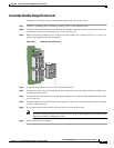
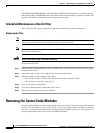
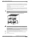
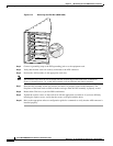
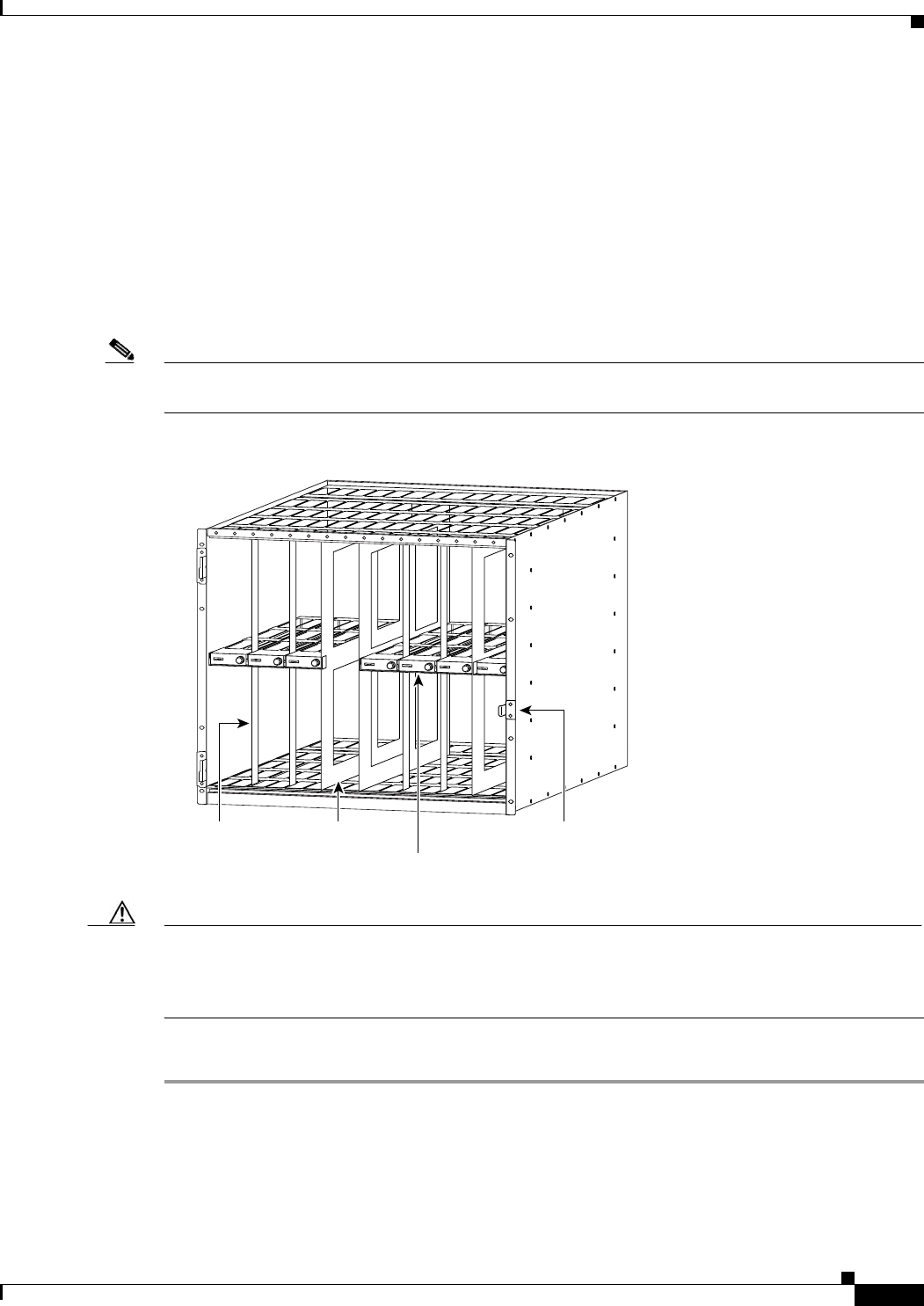
Figure 6-7 Center Guide Module Position in an MGX 8850 or MGX 8950 Chassis
Caution Even though most portions of the vertical guide brackets are insulated, it is recommended that you turn
off the power before removing the center guide modules. If you remove the center guide modules while
the power is on, you may short out the adjacent cards by making contact with the non-insulated leg ends
of a vertical support bracket.
Complete the following steps to remove the center guide modules:
Step 1 Connect a grounding strap to the ESD grounding jack or to the equipment rack.
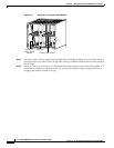
Step 2 Loosen the captive screw from the vertical support bracket (see Figure 6-8) using the appropriate
screwdriver.
Step 3 Carefully pull the bracket toward you.
17673
Door latch
Vertical support
bracket
Bulkhead
Center guide module