


5-12
Cisco MGX 8800/8900 Series Hardware Installation Guide
Releases 2 - 5.2, Part Number OL-4545-01, Rev. H0, May 2006
Chapter 5 Installing the Cisco MGX Switch or Gateway
Installing the MGX 8850 (PXM1E/PXM45) Switch, MGX 8850/B or MGX 8880 Media Gateway
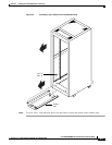
Step 4 Use a wrench to tighten a nut onto the threaded studs.
Measure Rack Space
Before you install the MGX 8850 switch and its related components, calculate the total rack space
required to install your system.
• See Table 3-1 on page 3-11 for the MGX 8850 switch dimensions and rack units (RUs) required.
• See Table 3-24 on page 3-58 for the MGX 8880 DC gateway dimensions and rack units (RUs) and
Table 3-25 on page 3-59 for the MGX 8880 AC gateway dimensions and rack units required.
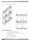
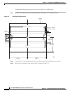
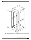
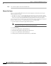
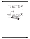
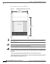
System components must be installed in the rack in the following sequence, beginning at the bottom of
the rack or cabinet (see Figure 5-5 for MGX 8850 and Figure 5-6 for MGX 8880):
1. AC power supply tray with power supply modules (optional)
Note On the MGX 8850, if a second AC power supply tray is used (optional), install it just above
the first AC power supply tray and below the air intake plenum.
2. Air intake plenum
3. Lower fan tray (MGX 8850 or MGX 8850/B only)
4. MGX 8850, MGX 8850/B or MGX 8880 (with optional door)
5. Upper fan tray (MGX 8850 or MGX 8850/B only)
6. Exhaust plenum (combined exhaust plenum/fan tray on MGX 8880)