


6-23
Cisco MGX 8800/8900 Series Hardware Installation Guide
Releases 2 - 5.2, Part Number OL-4545-01, Rev. H0, May 2006
Chapter 6 Maintaining the Cisco MGX Switch or Gateway
Installing or Removing Redundancy Connectors
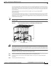
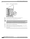
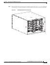
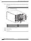
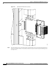
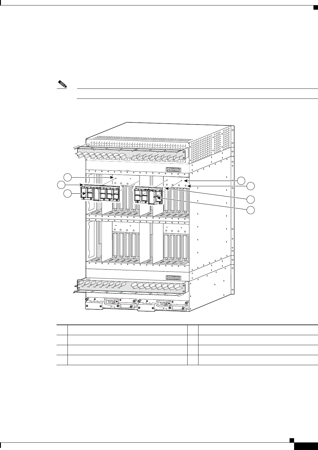
Step 4 Place the RCON assembly over the RCON mounting bar, positioning the RCON alignment flange over
the top edge of the bar and the RCON alignment pins through holes in the bar (See Figure 6-13).
• If you are installing the 1:5 RCON, there is a single mounting position on the mounting bar.
• If you are installing the 1:3 RCON, there are two mounting positions on the mounting bar, offset by
one slot. The 1:3 RCON in Figure 6-13 is shown in the left-hand mounting location.
Note Be careful not to bend or damage the pins on nearby back card connectors.
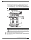
Figure 6-13 MGX 8850/B RCON Installation
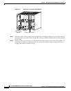
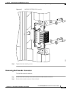
Step 5 Tighten the two RCON fasteners, first by hand and then using a screwdriver.
Step 6 Install additional RCONs, if desired. You can install up to four RCONs, on the left and right-hand side
of the top and bottom bay.
Step 7 Reinstall all back cards.
1 Mounting bar for RCON 5 Alignment holes for RCON
2 Alignment flange on 1:5 RCON assembly 6 Alignment flange on 1:3 RCON assembly
3 Mounting screw on 1:5 RCON assembly 7 Mounting screw on 1:3 RCON assembly
4 Left mounting location for 1:3 RCON
1
3
2
4
5
7
6
146505