


B-14
Cisco MGX 8800/8900 Series Hardware Installation Guide
Releases 2 - 5.2, Part Number OL-4545-01, Rev. H0, May 2006
Appendix
Redundancy Y-Cable
DC Power Connections
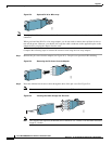
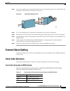
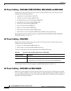
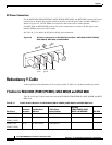
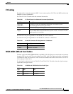
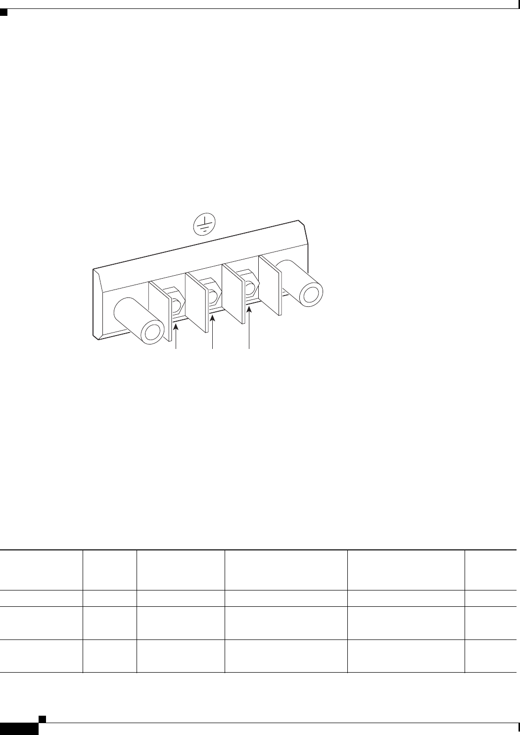
For the MGX 8850 (PXM1E/PXM45), MGX 8850/B, MGX 8950, and MGX 8880 systems, DC power
connections are made to the terminal block on the back of the DC power entry modules (PEMs), as
shown in Figure B-6. The DC PEMs are installed on the back of the air intake plenum.
For MGX 8830 or MGX 8830/B systems, DC power connections are made to the DC power entry
modules (PEMs) at the rear of the switch.
See Table B-13 for details on DC power cabling and connections.
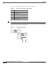
Figure B-6 DC Power Connections on DC PEM Terminal Block—MGX 8850 (PXM1E/PXM45),
MGX 8850/B, MGX 8950, and MGX 8880
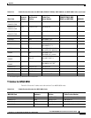
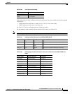
Redundancy Y-Cable
Y-cables provide card redundancy. This section contains Y cable Cisco product numbers by switch.
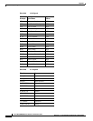
Y Cables for MGX 8850 (PXM1E/PXM45), MGX 8850/B and MGX 8880
Table B-14 lists the Y-cables used with various MGX 8850 (PXM1E/PXM45), MGX 8850/B, and MGX
8880 cards.
48 VDC
return
Safety
g
round
–48 VDC
38228
-48V
RTN
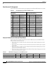
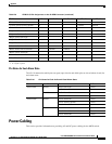
Table B-14 Y-Cable Product Numbers for MGX 8850 (PXM1E /PXM45), MGX 8850/B, and MGX 8880 Cards
Back Card
Connector
Hardware
Type/Standard
Interface
Y Cable Cisco
Product Number
MGX 8850
(PXM1E/PXM45), MGX
8850/B, and MGX 8880 MGX 8950
PXM-UI-S3/B RJ-45 CAB-SSIO-RJ45 x
PXM-UI-S3
PXM-UI-S3/B
RJ-45 EIA/TIA-232 CAB-5686-04 x x
PXM-UI-S3
PXM-UI-S3/B
RJ-45 T1 BITS clock CAB-5686-04 x