


5-136
Cisco MGX 8800/8900 Series Hardware Installation Guide
Releases 2 - 5.2, Part Number OL-4545-01, Rev. H0, May 2006
Chapter 5 Installing the Cisco MGX Switch or Gateway
Installing the Ferrite Bead on Ribbon Connectors
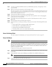
If the ferrite bead is closed, place the bead on a flat surface.
a. Insert a small flat-blade screwdriver into the recessed area under each of the two locking tabs.
b. Carefully pry outward to unlock the mechanism.
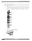
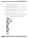
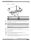
Step 2 Place the first open ferrite bead on the cable 8 inches from the end of the ribbon connector that is to be
attached to the RBBN-16-T1E1 back card (see Figure 5-86).
Snap the ferrite bead closed by pressing each half together until the two locking mechanisms snap firmly
shut.
Step 3 Place the second open ferrite bead on the same cable 60 inches from the end of the ribbon connector that
is to be attached to the RBBN-16-T1E1 back card.
Snap the ferrite bead closed by pressing each half together until the two locking mechanisms snap firmly
shut.
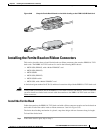
Step 4 To secure the beads, fasten one wire zip tie around the cable on each side of each bead.
Ensure that the ties are up against each side of the bead.
Step 5 (Optional) Repeat Step 1 through Step 4 for the other cable that connects to the RBBN-16-T1E1 back
card.
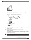
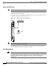
Figure 5-89 Place Two Ferrite Beads on the Cables that Lead to Connectors 3 and 4
80665
RBBN
16 -T1E1
ENBL
E1
T1
T
X
R
X
3
4
ENBL
E1
T1
21