


2-48
Cisco MGX 8800/8900 Series Hardware Installation Guide
Releases 2 - 5.2, Part Number OL-4545-01, Rev. H0, May 2006
Chapter 2 Illustrated Card List for MGX Switches and the MGX 8880 Media Gateway
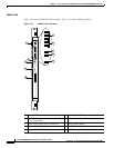
Front Cards
Note For information on PXM1E software features and configurations, refer to the Cisco MGX 8800/8900
Series Configuration Guide, Release 5.2. For technical specifications for the PXM1E cards, see the
“PXM1E Specifications” section on page A-3.
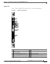
Module Configurations
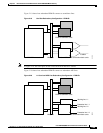
PXM1E card redundancy is preconfigured on the Cisco MGX switches. If PXM1Es are inserted in both
slots 7 and 8 on an MGX 8850 (PXM1E) switch or slots 1 and 2 on an MGX 8830 switch, they
automatically operate as redundant cards. If you install only one PXM1E in the switch, it operates as a
standalone card. It is recommended that you install two to provide fault tolerance for the PXM1E. If one
card goes down, a redundant card takes over.
Note For the PXM1E card to operate redundantly, Y-cabling or 1+1 card and APS line redundancy must be
present on the ATM and external clock ports on the back cards.
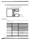
The following module configurations are supported for the PXM1E:
• Standalone.
• Card set redundancy (Y-cable)—Redundant PXM1Es must be placed in slots 1 and 2 for MGX 8830
or slots 7 and 8 for MGX 8850 (PXM1E).
• 1:1 APS line redundancy (intracard)—OC-3c interfaces only.
• 1+1 card and APS line redundancy (intercard)—on PXM1E-4-155 and PXM1E-8-155.
• IMA—PXM1E-16-T1E1 only.
Note For module configuration information, refer to Chapter 4, “Planning for Card Redundancy, Line
Redundancy, and Bulk Distribution”.