


5-97
Cisco MGX 8800/8900 Series Hardware Installation Guide
Releases 2 - 5.2, Part Number OL-4545-01, Rev. H0, May 2006
Chapter 5 Installing the Cisco MGX Switch or Gateway
Installing the MGX 8950 Switch
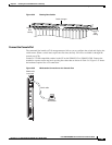
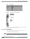
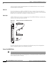
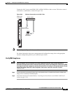
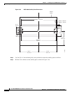
Connect the LAN 1 port on the PXM-UI-S3 or PXM-UI-S3/B to a hub or router. This hub or router is
connected to a workstation, as shown in Figure 5-64.
Figure 5-64 Ethernet Connection to the LAN 1 Port
Note The LAN 2 port in Figure 5-64 is not enabled.
For further information about server management and configuration setup, refer to the appropriate
software configuration guide for your switch and your release.
Verify EMI Compliance
Warning
Blank faceplates and cover panels serve three important functions: they prevent exposure to
hazardous voltages and currents inside the chassis; they contain electromagnetic interference (EMI)
that might disrupt other equipment; and they direct the flow of cooling air through the chassis. Do not
operate the system unless all cards, faceplates, front covers, and rear covers are in place.
Statement 1029
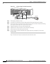
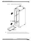
Step 1 If your switch has an (optional) front door, verify that the door is installed and closed and that each
empty slot is covered by a blank faceplate.
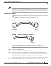
Step 2 Install the ferrite bead if needed. Refer to “Installing the Ferrite Bead on the PXM-UI-S3/B Card”
section on page 5-133.
PXM
UI-S3
C
P
M
P
A
L
1
N
L
2
N
A
L
A
A
R
M
E
X
T
C
L
K
1
E
X
T
C
L
K
2
44372
Workstation
Hub or router
Ethernet cable
PXM-UI-S3
back card