


5-127
Cisco MGX 8800/8900 Series Hardware Installation Guide
Releases 2 - 5.2, Part Number OL-4545-01, Rev. H0, May 2006
Chapter 5 Installing the Cisco MGX Switch or Gateway
Installing the MGX 8830 or MGX 8830/B Switch
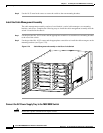
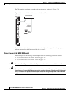
Connect AC Power to the Switch
Complete the following steps to connect AC power to the switch.
Note The AC power receptacle on the AC power supply tray is an IEC-type with a clamp. The AC voltage
range is 90 to 264 VAC. See Table 3-19 for information about the types of AC power cords.
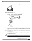
Step 1 Loosen the cable clamp around the AC receptacle on the AC power supply tray to allow clearance for
the cable connector.
Step 2 Firmly seat the cable plug in the AC receptacle on the back of the AC power supply tray.
Step 3 Tighten the clamp.
Caution Verify that the branch circuit power is off before you insert the power cable into the wall outlet.
Step 4 Plug the other end of the AC power cord into the wall outlet.
Step 5 Repeat Step 1 through Step 4 for a second AC power supply, if appropriate.
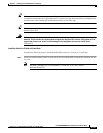
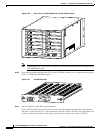
Note If only one AC power supply is used in your switch, install black faceplates to cover the slot for
the second AC power supply and the opening where the DC PEM would otherwise be installed.
If you are using DC power and only one DC PEM, cover the second DC PEM slot with a blank
faceplate.
Step 6 Turn on the power source and turn the power switch on.
Step 7 Verify that the fans are running by listening or feeling for air movement. The following LEDs should
be lit:
• The AC and DC LEDs on each power supply should be green.
• The Status LED on the PXM1Es should be green.
• The Standby LED on each service module should be yellow.
Connect DC Power to the Switch
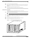
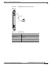
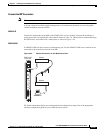
DC power is connected to one or two DC PEMs located on the MGX 8830 chassis rear panel. You must
supply the wiring from the DC source(s) to the DC PEM(s). The wiring should be 10 AWG (4 square
millimeters).
Warning
Be sure the power to the shelf is OFF at this point. DO NOT apply power until later.
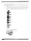
Complete the following steps to connect DC power to the MGX 8830:
Step 1 Locate the DC PEM(s) on the rear panel of the MGX 8830. (See Figure 5-80 for DC PEM location.)