


1-24
Cisco MGX 8800/8900 Series Hardware Installation Guide
Releases 2 - 5.2, Part Number OL-4545-01, Rev. H0, May 2006
Chapter 1 Product Overviews
Cisco MGX 8850 and MGX 8850/B Switches
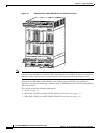
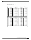
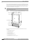
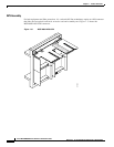
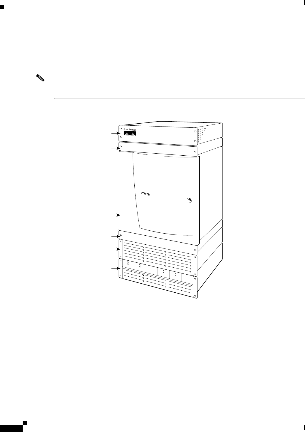
Figure 1-9 shows the hardware components that can be used with a Cisco MGX 8850 switch (viewed
from the front of the switch). This illustration also shows the optional AC power supply tray installed at
the bottom of the system. The switch can have an optional front door installed (as shown in Figure 1-9).
For the switch to be EMI compliant, either the optional front door must be installed on the switch or
blank faceplates must be installed to cover any empty slots.
Note The DC PEM is installed on the rear of the chassis. The APS assembly is not visible in the illustration
because it is installed inside the card cage.
Figure 1-9 Hardware Component Locations for a MGX 8850 or MGX 8850/B Switch—Front View
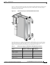
This section provides details about the following MGX 8850 or MGX 8850/B switch hardware
components:
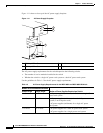
• AC Power Supply Tray, page 1-25
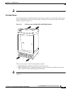
• Air Intake Plenum, page 1-27
• APS Assembly, page 1-28
• DC Power Entry Module, page 1-30
• Exhaust Plenum, page 1-32
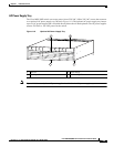
• Lower and Upper Fan Trays, page 1-32
• MGX 8850/B Redundancy Connectors, page 1-33
84419 ~
Exhaust plenum
Upper fan tray
Lower fan tray
Cisco MGX 8850 switch
Air intake plenum
AC power supply
tray (optional)
A
C
D
C
1
2
0
0
W
AC
DC
1
2
0
0
W
AC
DC
1200W
A
C
D
C
1200W