


5-59
Cisco MGX 8800/8900 Series Hardware Installation Guide
Releases 2 - 5.2, Part Number OL-4545-01, Rev. H0, May 2006
Chapter 5 Installing the Cisco MGX Switch or Gateway
Installing the MGX 8950 Switch
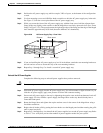
• Cisco cabinet configuration—The switch and hardware components (optional AC power supply tray,
air intake plenum, upper and lower fan trays, and exhaust plenum) are shipped front-mounted in the
enclosure, and the rear of each component is supported by a rear bracket.
When you are installing a MGX 8950 system in a 23-inch rack, the switch and hardware components
(optional AC power supply tray, air intake plenum, upper and lower fan trays, and exhaust plenum) need
to be mid-mounted in the rack. You need special mounting brackets to mid-mount the components in a
23-inch rack (mounting kit, Cisco Part Number MGX-MNT23-8950).
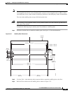
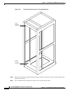
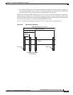
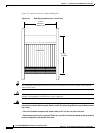
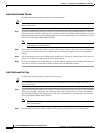
Figure 5-36 shows the mounting rail distances for front, middle, and rear-mounting rails.
Figure 5-36 Mounting Rail Distances
Module
Rear rail
5.0 in.
(12.7 cm)
10.0 in. (25.4 cm)
19.86 in. (50.44 cm)
MGX 8950 Depth 24 in. (70 cm)
Allowable intermediate
rail positions
Front rail
66048