


5-81
Cisco MGX 8800/8900 Series Hardware Installation Guide
Releases 2 - 5.2, Part Number OL-4545-01, Rev. H0, May 2006
Chapter 5 Installing the Cisco MGX Switch or Gateway
Installing the MGX 8950 Switch
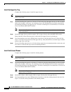
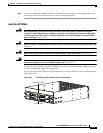
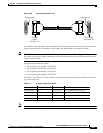
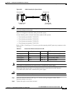
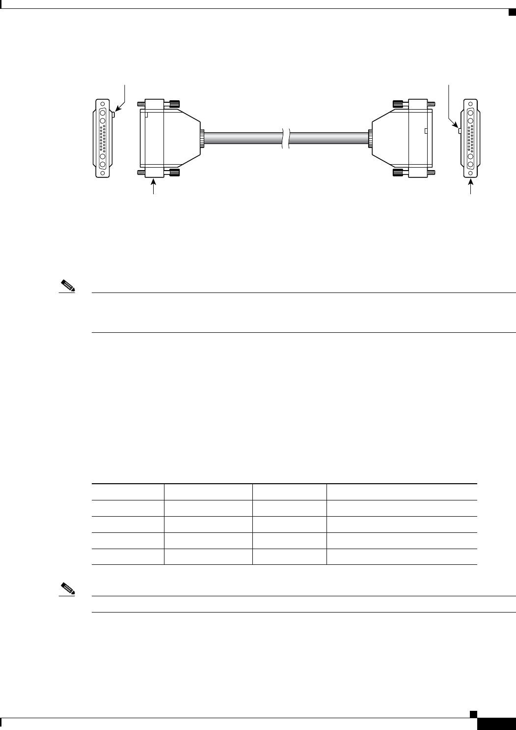
Figure 5-48 Interconnect Cable for AC
The shrouds on the AC cables and the receptacles on the card cage and power trays are keyed to ensure
proper connections. Do not attempt to insert cables into shrouds that are not keyed for them.
Note The AC power interconnect cables from each tray must be connected to the backplane. If the cables are
not connected, the power supply monitoring circuit will mistake this as voltage failure and will result in
a tripped circuit breaker.
You will need the following cables:
• Cisco Systems part number 72-2420-XX
• Cisco Systems part number 72-2421-XX
• Cisco Systems part number 72-2422-XX
• Cisco Systems part number 72-2423-XX
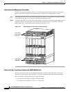
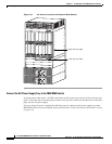
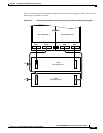
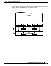
See Table 5-4 and Figure 5-49 for assistance with connecting the AC power tray connectors to the card
cage and power trays:
Note Cisco highly recommends that you install and use a redundant AC power supply.
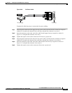
43982
To power
supply
(PS tray 1 J1)
To card cage
(card cage A1)
Card Cage A1
PS Tray 1
J1
Alignment keyAlignment key
Table 5-4 AC Power Cable Connections
Cable Label Card Cage Connect Cable Label Power Tray Connector
Card Cage A1 PSA 1 PS Tray 1 J1 J1 on primary (top) PS Tray
Card Cage B1 PSB 1 PS Tray 2 J1 J1 on secondary (bottom) PS Tray
Card Cage B2 PSB 2 PS Tray 2 J2 J2 on secondary PS Tray
Card Cage A2 PSA 2 PS Tray 1 J2 J2 on primary PS Tray