


3-35
Cisco MGX 8800/8900 Series Hardware Installation Guide
Releases 2 - 5.2, Part Number OL-4545-01, Rev. H0, May 2006
Chapter 3 Preparing for Installation
Site Requirements for the MGX 8950 Switch
Power Requirements
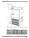
The system can accept power from either an optional AC source (AC power supply tray) or a DC source
(DC PEM). Table 3-12 details the power specifications for both the AC and DC sources.
Warning
This unit is intended for installation in restricted access areas. A restricted access area is where
access can only be gained by service personnel through the use of a special tool, lock and key, or
other means of security, and is controlled by the authority responsible for the location.
Statement 37
Note In the United States, restricted access is defined in Articles 10-116, 10-117, and 10-118 of the National
Electrical Code ANSI/NFPA 70.
The following sections provide additional information about power:
• AC Power, page 3-36
• DC Power, page 3-37
• Power Consumption Calculation Tables, page 3-37
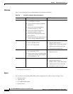
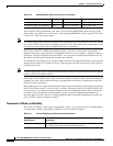
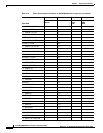
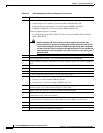
Table 3-12 Power Specifications for the MGX 8950 System
Specification Description
Power input voltage
• AC source: Normal operating range is 200 to 240 VAC, 47 to 63 Hz. The
maximum voltage range is 180 to 254 VAC.
Note The AC power source must be within 6 feet (1.8 meters) of the
system and easily accessible.
• DC source: –42 to –56 VDC.
AC system current
requirements
Configuration-dependent: Use Table 3-6 for exact requirements. For general
planning purposes: 14.4 A at a nominal voltage of 200 VAC. At the minimum
voltage limit of 180 VAC, the current draw is a maximum of 21 A.
DC system current
requirements
Configuration-dependent: Use Table 3-6 for exact requirements. For general
planning purposes: 76 A (37.5 A per feed) at nominal -48 VDC; 86 A (43 A
per feed) at -42 VDC minimum.
Input AC power
connector
For a list of the AC power plugs for domestic and international use, see
Table 3-14 on page 3-39.
DC input connections Three-position terminal block for 6 AWG wire (10 square millimeters), and
no. 10 screw lugs designed for 6 AWG wire. The customer supplied wire
must be terminated with a terminal lug that accepts no. 10-32 screws.