


5-45
Cisco MGX 8800/8900 Series Hardware Installation Guide
Releases 2 - 5.2, Part Number OL-4545-01, Rev. H0, May 2006
Chapter 5 Installing the Cisco MGX Switch or Gateway
Installing the MGX 8850 (PXM1E/PXM45) Switch, MGX 8850/B or MGX 8880 Media Gateway
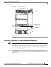
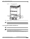
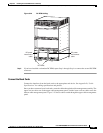
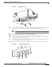
Figure 5-28 DC PEM—Rear View
Step 3
Measure enough wire (6 AWG [10 square mm] or larger three-wire solid or stranded copper wire with
insulation rating for 140°F [60°C]) to connect the DC PEM terminal block to the power source.
Note It is recommended that you use the Panduit LC AS6-10-L.
Step 4 Cut the ends of the wire so that the ends are straight, not slanted.
Step 5 Measure 1/4 inch (6 mm) up from one end of the wire and place a mark at that point.
Step 6 Use a wire stripper to remove 1/4 inch (6 mm) of the covering from the end of the wire. Trim the end of
the covering so that it is straight, not slanted.
Step 7 Attach a ring or space lug on the end of copper wire you prepared in Step 6. The stripped part of the wire
must be fully inserted so that no bare wire is exposed.
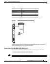
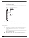
Step 8 Attach the end of the wire with the ring or space lug to the 48-VDC return, as shown in Figure 5-29.
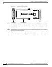
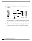
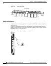
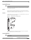
Figure 5-29 Terminal Block on the DC PEM
J1
-48V
OFF
ON
RTN
DC OK
15685
DC OK LED
Plastic cover
Circuit breaker
J1 output
connector
Terminal
block 1
(DC input)
48 VDC
return
Safety
g
round
–48 VDC
38228
-48V
RTN