


5-130
Cisco MGX 8800/8900 Series Hardware Installation Guide
Releases 2 - 5.2, Part Number OL-4545-01, Rev. H0, May 2006
Chapter 5 Installing the Cisco MGX Switch or Gateway
Installing the MGX 8830 or MGX 8830/B Switch
Step 8 If you have a redundant DC PEM installed in your MGX 8830, repeat Step 1 through Step 7 for the
second DC PEM.
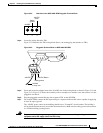
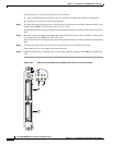
Step 9 Before you turn on the system power, check the supply voltage.
The screws at positions 1 and 3 on the pluggable terminal block are convenient measuring points. Also,
check the impedance between the safety ground (screw at location 2 on the pluggable terminal block)
and the chassis. It should be close to 0.
Step 10 Verify that the DC PEM circuit breakers are in the OFF position.
Step 11 Turn on the source power, and check the voltage at the screws at positions 1 and 3 on the pluggable
terminal block for all installed PEMs.
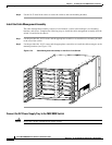
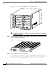
Step 12 Turn off the source power and proceed to the “Install the Cable Management Assembly” section on
page 5-122.
Step 13 Turn on the power source and turn the power switch on.
Step 14 Verify that the fans are running by listening or feeling for air movement. The following LEDs should
be lit:
• The AC and DC LEDs on each power supply should be green.
• The DC OK LED on each DC PEM should be green.
• The Status LED on the PXM1Es should be green.
• The Standby LED on each service module should be yellow.
Connect the External Clock
This step is optional. For information, see “Connect the External Clock” section on page B-7.
Connect the Alarms
Note This step is optional.
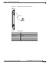
Dry contact relay closures are available for forwarding MGX 8830 switch alarms to an alarm system.
Separate visual and audible alarm outputs are available for critical, major, and minor alarm outputs, and
the outputs are provided through the use of a DB-15 connector on the PXM user interface back card
(PXM-UI-S3 and PXM-UI-S3/B).
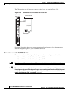
Complete the following steps to connect the external clock:
Step 1 Verify that you have a PXM-UI-S3 or PXM-UI-S3/B back card installed in slots 1 and 2 in the rear bay
of the switch.
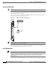
Step 2 Connect the DB-15 cable to the ALARM port on the PXM-UI-S3 or PXM-UI-S3/B back card.
Note See Appendix B, “Cable Specifications” for cable requirements.
Step 3 Connect the other end of the cable to the alarm source.