


5-124
Cisco MGX 8800/8900 Series Hardware Installation Guide
Releases 2 - 5.2, Part Number OL-4545-01, Rev. H0, May 2006
Chapter 5 Installing the Cisco MGX Switch or Gateway
Installing the MGX 8830 or MGX 8830/B Switch
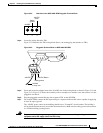
Step 6 Repeat Step 1 through Step 5 with the other AC power supply cable to connect the second AC
power supply.
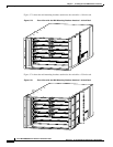
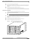
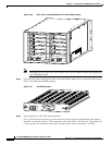
Note When viewing the switch from the rear, the AC power supply cable from the left AC power
supply is connected to the fixture on the left side of the midplane. Likewise, the AC power
supply cable from the right AC power supply is connected to the fixture on the right side of the
midplane. (See Figure 5-77.)
Caution Do not plug in the AC power cord at this time.
Connect the Back Cards
Connect the interfaces from the back cards to the appropriate end device. See Appendix B, “Cable
Specifications” for cabling specifications and pinouts.
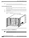
Once you have connected your back cards, route the cables through the cable management assembly. The
left card set cables run to the left cable management panel, and the right card set cables run to the right
cable management panel.
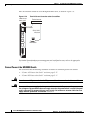
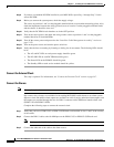
Connect the Console Port
The command line interface (CLI) management tool allows you to configure the switch and display the
switch status. When a switch starts up for the first time, the only CLI access available is through the
console port (CP).
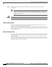
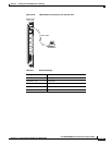
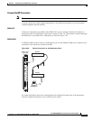
Connect a VT-100 compatible terminal to the CP on the PXM-UI-S3 or PXM-UI-S3/B. Connect the
terminal to a power source and set it up using the values that are shown in Table 5-8. Figure 5-78 shows
the hardware required for a CP connection.