


B-8
Cisco MGX 8800/8900 Series Hardware Installation Guide
Releases 2 - 5.2, Part Number OL-4545-01, Rev. H0, May 2006
Appendix
Control and Clock Cabling
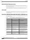
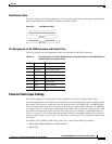
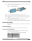
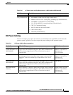
Figure B-2 Optional RJ-45 to Wire-wrap
Note The eight pins of the adapter are marked and have a one-to-one correlation to the eight lines on the RJ-45
connector.
When you install the RJ-45 to wire-wrap adapter, you do not need to remove the card from its slot or
turn off the power. However, you should wire-wrap the cable conductors to the applicable pins on the
adapter before you plug the adapter into the card.
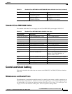
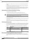
Complete the following steps to connect the external clock using the wire-wrap adapter:
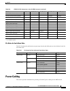
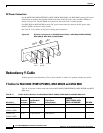
Step 1 Remove the pin cover from the adapter (see Figure B-3). The pin cover provides ESD shielding.
Figure B-3 Removing the Pin Cover from the Adapter
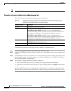
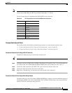
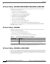
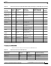
Step 2
Insert the shielded clock source cable through the hole of the pin cover. See Figure B-4.
Note You must use a shielded clock source cable to ensure EMI containment.
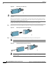
Figure B-4 Inserting the Cable through the Pin Cover
Note The length of the exposed (unshielded) wires should be 2 to 4 inches. The maximum allowable
length is 4 inches.
52804
52803
5
6
7
8
52805
1
2
3
4