


B-17
Cisco MGX 8800/8900 Series Hardware Installation Guide
Releases 2 - 5.2, Part Number OL-4545-01, Rev. H0, May 2006
Appendix
Frame Relay Cabling
See Table B-19 for details on SMB pin functions.
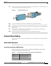
Frame Relay Cabling
This section describes the cabling and connector pin assignments for the Frame Relay cards.
Note The Frame Relay Cabling section does not apply to the MGX 8950 switch or MGX 8880 gateway.
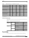
T1 Cabling
T1 trunk cables connect the customer DSX-1 cross-connect point or T1 channel service unit (CSU) to
the Cisco MGX 8850 or MGX 8830 switch at the T1 back card.
See Table B-20 for T1 trunk cable and connector information.
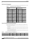
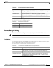
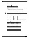
Table B-18 E3 Trunk Cable and Connector Information
Cable Parameter Description
Type 75-ohm coaxial cable (RG-59 B/U for short runs, AT&T 734A for longer
runs). Two per E3 line (transmit and receive).
Maximum length 100 feet between the Cisco MGX 8850 switch and the CS/DSU.
450 feet maximum between the Cisco MGX 8950 switch and the DSX-3.
Connector Terminated in male SMB. Rx is received from trunk; Tx is transmitted to
trunk.
Table B-19 E3 Connector Pin Functions
Connector Description
Rx SMB Receive E3 from trunk
Tx SMB Transmit E3 to trunk
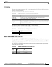
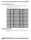
Table B-20 T1 Trunk/Circuit Line Cable and Connector Specifications
Cable Parameter Description
Cable type Western Electric 22 AWG, ABAM individually shielded twisted pair (100
ohm balanced). Two pair per T1 line (one transmit and one receive).
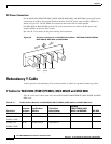
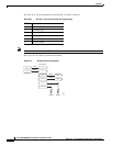
Cable connector RJ-48C male. (Figure B-7 illustrates the RJ-48 connector schematic.)
Maximum cable length 655 feet (199.64 meters) maximum between the Cisco MGX 8850 or
MGX 8830 switch and the first repeater or CSU. A selection of cable
length equalizers is available.