


4-17
Cisco ASR 1000 Series Aggregation Services Routers Hardware Installation and Initial Configuration Guide
OL-13208-03
Chapter 4 Cisco ASR 1006 Router Overview and Installation
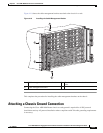
Attaching a Chassis Ground Connection
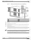
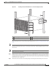
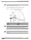
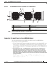
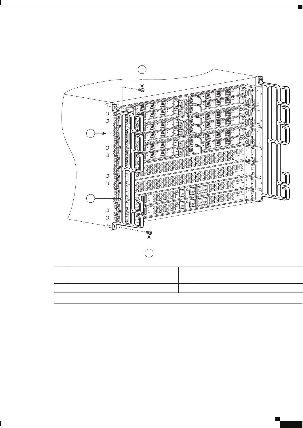
Figure 4-10 shows the cable-management brackets attached to the chassis in a rack.
Figure 4-10 Installing the Cable-Management Bracket
This completes the procedure for installing the cable-management brackets on the chassis.
Attaching a Chassis Ground Connection
Connecting the Cisco ASR 1006 Router chassis to earth ground is required for all DC powered
installations and any AC powered installation where compliance with Telcordia grounding requirements
is necessary.
1 Cable-management bracket screw location 3 Chassis front rack-mount bracket and ear
holes
2 Cable-management bracket
280036
S
P
A
-
4
XO
C
3
-
P
O
S
S
T
AT
US
0
1
2
3
C
/A
A/
L
C/
A
A
/L
C/
A
A
/
L
C/
A
A
/
L
S
P
A
-
4
XO
C
3
-
P
O
S
S
TATUS
0
1
2
3
C
/A
A/
L
C/A
A
/L
C/
A
A
/L
C/
A
A/L
SP
A
-
4
X
O
C
3
-
P
O
S
S
T
AT
US
0
1
2
3
C/
A
A/
L
C/
A
A
/L
C
/A
A
/L
C/A
A
/
L
SP
A
-
4
X
O
C
3
-
P
O
S
S
TATUS
0
1
2
3
C/
A
A
/
L
C
/A
A
/L
C
/
A
A
/
L
C/A
A
/L
SP
A
-
4
X
O
C
3
-
P
O
S
S
TATUS
0
1
2
3
C/
A
A
/L
C
/
A
A/L
C
/
A
A
/L
C/A
A
/L
SP
A
-
4
X
O
C
3
-
P
O
S
S
T
AT
US
0
1
2
3
C/
A
A/L
C/
A
A/L
C
/
A
A
/L
C
/A
A
/L
S
P
A
-
4
X
O
C
3
-
P
O
S
S
TATUS
0
1
2
3
C/
A
A/L
C/
A
A/
L
C
/A
A
/
L
C
/A
A
/L
S
P
A
-
4
X
O
C
3
-
P
O
S
S
T
A
T
US
0
1
2
3
C/
A
A/L
C/
A
A/
L
C/A
A
/L
C/A
A
/L
S
P
A
-
4
XO
C
3
-
P
O
S
S
TATUS
0
1
2
3
C/A
A/L
C/A
A/
L
C/A
A
/
L
C/
A
A
/L
S
P
A
-
4
XO
C
3
-
P
O
S
S
T
AT
US
0
1
2
3
C/A
A
/
L
C
/A
A
/
L
C/A
A/L
C/
A
A
/L
S
P
A
-
4
XO
C
3
-
P
O
S
S
TATUS
0
1
2
3
C/
A
A
/L
C/
A
A
/
L
C/A
A/
L
C/
A
A
/L
S
P
A
-
4
XO
C
3
-
P
O
S
S
T
AT
US
0
1
2
3
C/
A
A
/L
C/
A
A/
L
C/
A
A
/
L
C/
A
A
/L
1
1
2
3