


5-26
Cisco ASR 1000 Series Aggregation Services Routers Hardware Installation and Initial Configuration Guide
OL-13208-03
Chapter 5 Cisco ASR 1004 Router Overview and Installation
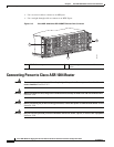
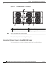
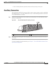
Connecting Power to Cisco ASR 1004 Router
• An earth ground cable is required for each DC PDU. We recommend that you use at least 6-AWG
multistrand copper wire. This wire is not available from Cisco Systems; it is available from any
commercial cable vendor.
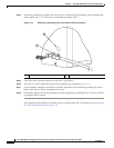
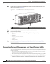
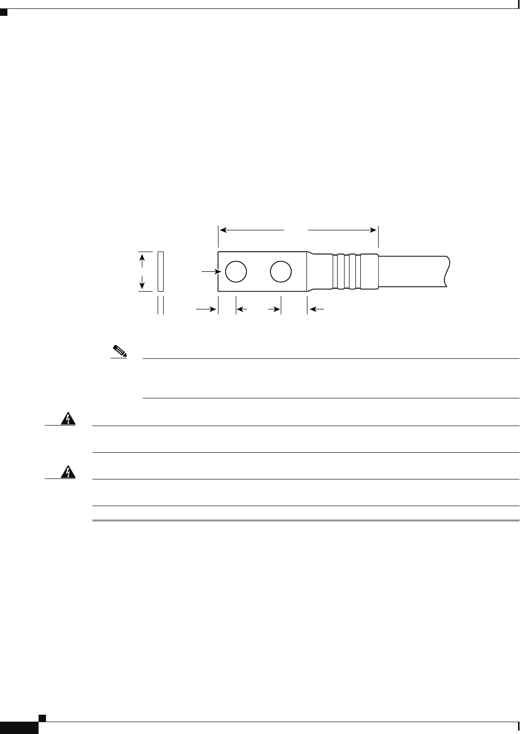
The ground wire cable lug should be dual-hole (as shown in Figure 5-18) and able to fit over M6
terminal studs at 0.625-inch (15.88-mm) centers. Recommended lug terminal wire size Panduit part
number:
–
LCD8-14A-L for 8AWG wire size
–
LCD6-14A-L for 6AWG wire size
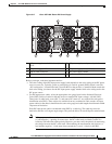
Figure 5-18 DC Input Power Cable Lug
Note To avoid hazardous conditions, all components in the area where DC input power is
accessible must be properly insulated. Therefore, before installing the DC cable lugs, be sure
to insulate the lugs according to the manufacturer’s instructions.
Warning
When you install the unit, the ground connection must always be made first and disconnected last.
Statement 1046
Warning
When you install the unit, the ground connection must always be made first and disconnected last.
Statement 1046
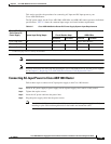
To connect the Cisco ASR 1004 Router DC power supply, follow these steps:
Step 1 Make certain that the chassis grounding is connected before you begin installing the DC power supply.
Step 2 Locate the terminal block and remove the plastic cover.
a. Unscrew and remove the two screws.
b. Slide the plastic cover off of the terminal block.
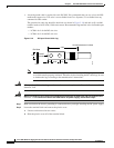
Crimp area
25527
2.24
0.48
0.08
0.25 0.370.63
End View
Ø 0.267
2 holes
All measurements in inches