


A-4
Cisco ASR 1000 Series Aggregation Services Routers Hardware Installation and Initial Configuration Guide
OL-13208-03
Appendix A Cisco ASR 1000 Series Routers Specifications
Cisco ASR 1006 Router Specifications
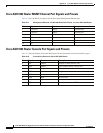
Cisco ASR 1006 Router Auxiliary Port Signals and Pinouts
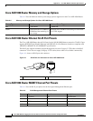
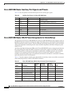
Table A-6 lists the pinouts of the dual RJ-45 ports for the auxiliary port signals.
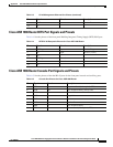
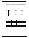
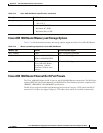
Cisco ASR 1006 Router DB-25 Pinout Assignments for Alarm Relays
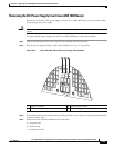
The alarm ports for the Cisco ASR 1006 Router (and Cisco ASR 1004 Router) power supplies reside on
the DB-25 connector on the face of the power supply. The alarm ports are relay contact closures that the
IOS environmental software controls. The environmental monitoring functions of the system can include
voltage and temperature monitoring for the router installed components and failure sensing for power
supply fan tray.
Any alarms that light the front panel LEDs on the Cisco ASR1000-RP1 causes a contact closure between
the corresponding pins within the DB-25 alarm port of both power supplies. In the DB-25 connector,
each alarm consists of a three-pin set containing a common pin, a normally open pin, and a normally
closed pin. The connections that describe alarm activity are Alarm off (Common is connected to
normally closed and normally open is disconnected) and Alarm on (Common is connected to normally
open and normally closed is disconnected).
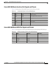
Table A-7 lists the common, normally open, and normally closed relay contacts accessible to an external
alarm monitoring facility by means of the DB-25 connector.
Table A-6 Auxiliary Port Pinouts for Cisco ASR 1006 Router
Pin Signal Direction Description
1
RTS Out Request to Send
2
DTR Out Data Terminal Ready (always On)
3
TXD Out Transmit Data
4
RI — Ring Indicator
5
GND —
6
RXD In Receive Data
7
DSR/DCD In Data Set Ready/Data Carrier Detect
8
CTS In Clear to Send
Table A-7 Cisco ASR 1006 Router DB-25 Alarm Connector Pinout Assignments
Signal Description
Common
(CM)
Normally
Open (NO)
Normally
Closed (NC)
SPARE
CRTAA Critical Audible Alarm 2 1 14
MAJAA Major Audible Alarm 16 3 15
MINAA Minor Audible Alarm 5 4 17
CRTVA Critical Visual Alarm 19 6 18
MAJVA
Major Visual Alarm
8 7 20
MINVA
Minor Visual Alarm
9
SPARE SPARE—unused pin
reserved for future use
10, 11, 12, 13