


4-25
Cisco ASR 1000 Series Aggregation Services Routers Hardware Installation and Initial Configuration Guide
OL-13208-03
Chapter 4 Cisco ASR 1006 Router Overview and Installation
Connecting Power to Cisco ASR 1006 Router
To connect the DC power supply, follow these steps:
Step 1 Make certain that the chassis grounding is connected before you begin installing the DC power supply.
Step 2 Locate the stud on the DC power supply for the GND connection which must be connected first and
follow these steps:
a. Using the grounding lug, replace the washers and Kepnut screw in the following order.
–
Flat washer
–
Grounding cable lug
–
Kepnut screw
b. Tighten the Kepnut screws on the power supply studs.
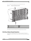
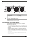
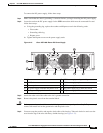
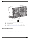
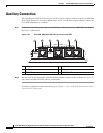
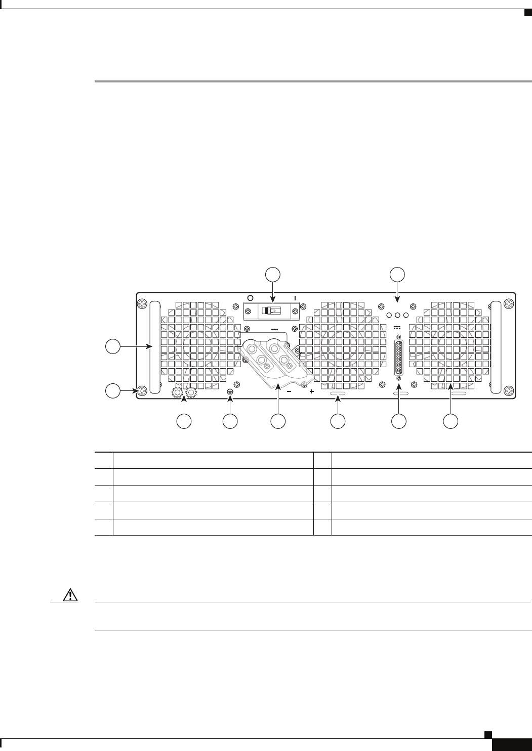
Figure 4-16 Cisco ASR 1006 Router DC Power Supply
Step 3 Attach the other end of the cable to the site’s ground connection.
Step 4 Remove the plastic cover from the terminal block.
Caution Before you continue to install the terminal block ground wires, stop and perform Step 5. To prevent any
contact with metal lead on the ground wire and the plastic cover.
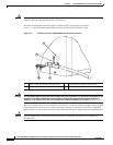
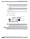
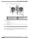
Step 5 You must wrap the positive and negative lead cables with sleeving. Take each lead wire and cover the
area from the lug to the wire with heavy shrink sleeving (see
Figure 4-17).
1 Fans 6 DC Power supply earth ground lugs
2 DB-25 alarm connector 7 DC Power supply captive screws
3 Tie-wrap tabs 8 DC Power supply handle
4 DC power supply terminal and plastic cover 9 DC power supply On (|) /Off (O) switch
5 Earth grounding symbol 10 DC power supply LEDs
OFF
280023
OUTPUTINPUT INPUT
FAIL OK OK
ALARMS
60V
1A MAX
This unit might have more than one power supply connection. All connections must be removed to de-energize the unit.
-48/-60V 40A
55
2 145 36
7
8
9 10