


6-36
Cisco ASR 1000 Series Aggregation Services Routers Hardware Installation and Initial Configuration Guide
OL-13208-03
Chapter 6 Cisco ASR 1002 Router Overview and Installation
Connecting Cables
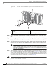
Step 2 Run the cable up and through the cable-management bracket and connect the other end of the RJ-45
cable to the RJ-45 adapter (
Figure 6-26).
Step 3 Connect the adapter to your video terminal to complete the cable connection.
Step 4 Power on your video terminal.
Step 5 Configure your video terminal to match the following default console port settings:
• 9600 baud
• 8 data bits
• No parity generation or checking
• 1 stop bit
• No flow control
Step 6 Go to the “Connecting Cables” section on page 6-36 to continue the installation.
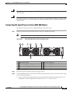
Connecting Cables
Keep the following guidelines in mind when connecting external cables to the Cisco ASR 1002 Router:
• To reduce the chance of interference, avoid crossing high-power lines with any interface cables.
• Verify all cabling limitations (particularly distance) before powering on the system.
Auxiliary Connection
This asynchronous EIA/TIA-232 serial port (AUX) is used to connect a modem to the Cisco ASR 1000
Series Route Processor 1 for remote administrative access. Use the following procedure to connect the
Cisco
ASR 1002 Router to a modem.
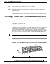
Step 1 Connect one end of the modem cable to the RJ-45 port on the primary Cisco ASR 1000 Series Route
Processor 1, labeled AUX. For the AUX port connection, see
Figure 6-18.
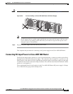
Step 2 Run the cable up and through the cable-management bracket and connect the other end of the cable to
your modem.
If you have completed all cable connections, go to, Chapter 7, “Cisco ASR 1000 Series Routers Power
Up and Initial Configuration.”