


8-36
Cisco ASR 1000 Series Aggregation Services Routers Hardware Installation and Initial Configuration Guide
OL-13208-03
Chapter 8 Replacing Cisco ASR 1000 Series Routers Field-Replaceable Units
Removing and Replacing a DC Power Supply in Cisco ASR 1004 Router
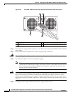
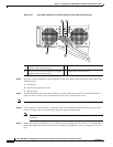
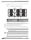
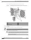
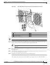
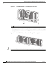
Figure 8-26 shows the DC power supply terminal block with lead wires connected.
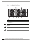
Figure 8-26 Cisco ASR 1004 Router DC Power Supply Terminal Block Lead Wire Connection
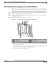
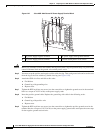
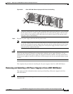
Step 5 Locate the power supply ground stud (Figure 8-20). Remove the earth ground (GND) cable from the DC
power supply.
Step 6 Loosen and remove the Kepnut screw, washer, and ground lug in that order.
Warning
When installing the unit, the ground connection must always be made first and disconnected last.
Step 7 Loosen the captive screws on the DC power supply.
Note Two power supplies must be installed in the chassis at all times to ensure sufficient cooling. The
system fans are inside the power supply units and must spin for cooling. Because all the system
fans can be powered by one power supply, the second power supply unit does not have to be
powered on, but it must be installed.
1 Ground stud and wire 4 Flat washer
2 Ground lug nut 5 Kepnut screw
3 Earth ground symbol
280187
2
5 4 3
1