


6-33
Cisco ASR 1000 Series Aggregation Services Routers Hardware Installation and Initial Configuration Guide
OL-13208-03
Chapter 6 Cisco ASR 1002 Router Overview and Installation
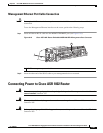
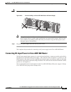
Connecting Power to Cisco ASR 1002 Router
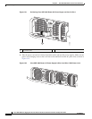
This section describes how to connect the DC power supply in a Cisco ASR 1002 Router.
Note The color coding of the DC-input power supply leads depends on the color coding of the DC power
source at your site. Typically, green or green/yellow is used for ground. Make certain the lead color
coding you choose for the DC-input power supply matches lead color coding used at the DC power
source.
Warning
When you install the unit, the ground connection must always be made first and disconnected last.
Statement 1046
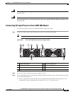
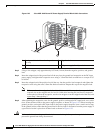
Step 1 At the rear of the router, check that the power supply Standby switch is in the Standby (see Figure 6-25)
position.
Step 2 Ensure that the negative and positive leads are disconnected from the site power source.
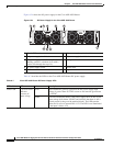
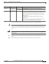
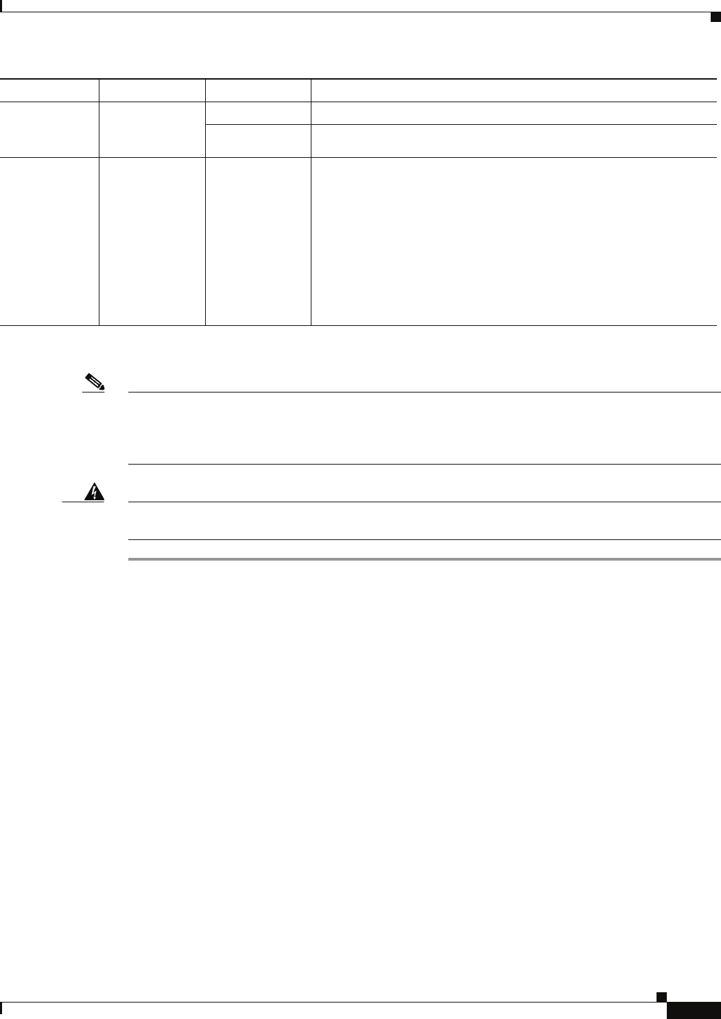
FAN OK A bi-color LED
indicates power
supply fan status
Green The LED illuminates s green when all fans are operational.
Red The LED illuminates red when a fan failure is detected.
OUTPUT FAIL Power supply
activity
Red When the LED is off, it signals that the DC output voltage are within
the normal operating range. Output voltage between the minimum and
maximum limits will not create an output fail alarm, and output
voltages below the minimum or above the maximum will create an
Output Fail alarm.
Led illuminates red to indicate that the DC output is out of the
specified range.
When you turn the power supply on, the red LED illuminates for two
to three seconds to test LED operation before going off.
LED Label LED Color Description