


8-27
Cisco ASR 1000 Series Aggregation Services Routers Hardware Installation and Initial Configuration Guide
OL-13208-03
Chapter 8 Replacing Cisco ASR 1000 Series Routers Field-Replaceable Units
Removing and Replacing a Cisco ASR 1006 Router Power Supply
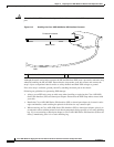
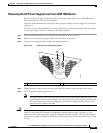
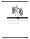
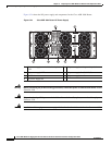
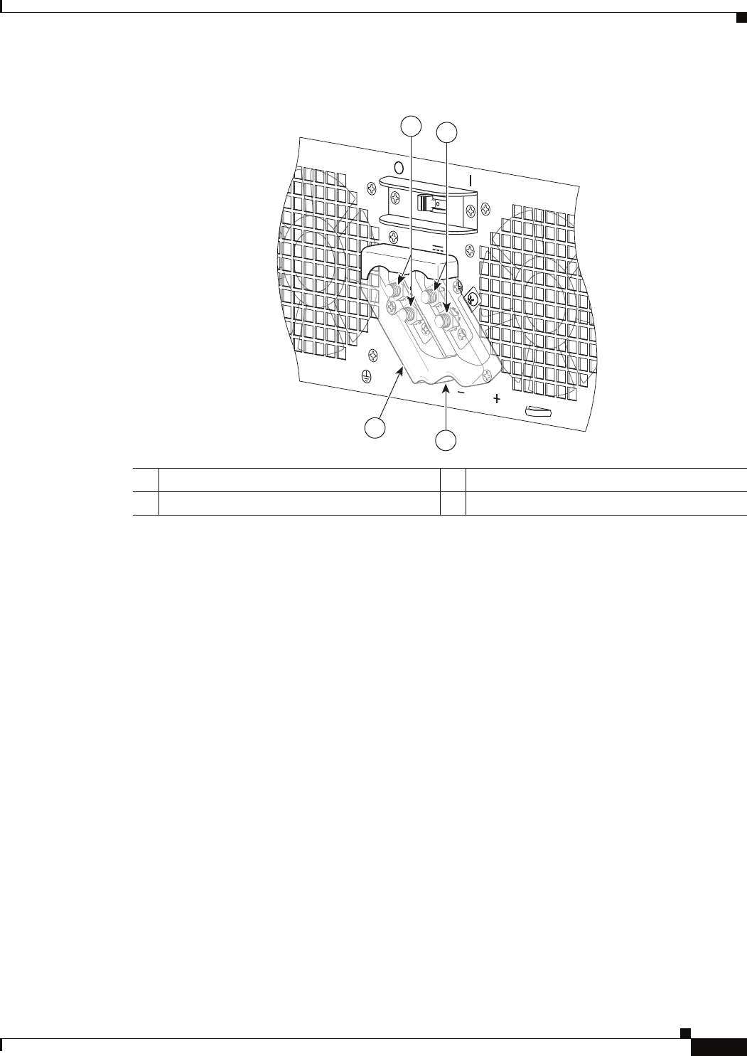
Figure 8-19 Cisco ASR 1006 Router DC Power Supply Terminal Block and Plastic Cover
Step 5 Remove the slotted plastic cover from the terminal block (Figure 8-19).
a. Loosen and remove the single screw on the plastic cover. The plastic cover has slots that help to slide
it out diagonally from the terminal block.
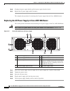
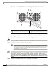
b. Using a nut driver (7/16 size), unsrew the positive kepnut, positive cable, and the flat washer, in that
order.
The terminal block houses two double-hole barrel lugs.
c. Follow Step 4b and remove the negative cable.
Figure 8-20 shows the DC power supply terminal block with cables connected.
1 Negative terminal 3 Plastic cover slotted area
2 Positive terminal 4 Terminal block plastic cover
This unit might have mo
re than one power supply connection. All connections must be
remov
OFF
55
-48/-60V 40A
280027
3
4
1
2