


8-44
Cisco ASR 1000 Series Aggregation Services Routers Hardware Installation and Initial Configuration Guide
OL-13208-03
Chapter 8 Replacing Cisco ASR 1000 Series Routers Field-Replaceable Units
Removing and Replacing a Cisco ASR 1002 Router Power Supply
Warning
Before performing any of the following procedures, ensure that power is removed from the DC circuit.
Statement 1003
Warning
Only trained and qualified personnel should be allowed to install, replace, or service this equipment.
Statement 1030
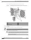
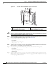
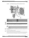
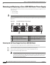
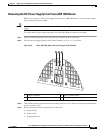
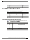
Figure 8-33 shows the DC power supply and components for the Cisco ASR 1002 Router.
Figure 8-33 Cisco ASR 1002 Router DC Power Supply
Warning
Before performing any of the following procedures, ensure that power is removed from the DC circuit.
Statement 1003
Warning
Only trained and qualified personnel should be allowed to install, replace, or service this equipment.
Statement 1030
Warning
Installation of the equipment must comply with local and national electrical codes.
Statement 1074
1 DC power supply ESD socket 6 DC power supply captive installation screw
2 DC power supply slot 0 label 7 DC power supply slot 1 label
3 DC power supply switch Standby/On (I)
(standby symbol is a broken circle with a
vertical line through the top of it)
8 Earth ground (GND)
4 DC power supply LEDs 9 Positive lead
5 Fan 10 Negative lead
280289
OUTPUTINPUT
FAIL
OK OK
FAN
-48V/-60V 16A
This unit might have more than
one power supply connection.
All connections must be removed
to de-energize the unit.
OUTPUTINPUT
FAIL
OK OK
FAN
-48V/-60V 16A
This unit might have more than
one power supply connection.
All connections must be removed
to de-energize the unit.
9 810
4 5 63
0
1
7
1
2