


8-24
Cisco ASR 1000 Series Aggregation Services Routers Hardware Installation and Initial Configuration Guide
OL-13208-03
Chapter 8 Replacing Cisco ASR 1000 Series Routers Field-Replaceable Units
Removing and Replacing a Cisco ASR 1006 Router Power Supply
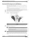
Step 6 Grasping the power supply handles, pull the power supply from the chassis.
Step 7 Replace the AC power supply within 5 minutes.
This completes the procedure for removing the AC power supply from the Cisco ASR1006 chassis.
Replacing the AC Power Supply in Cisco ASR 1006 Router
This section provides information about installing an AC power supply in the Cisco ASR 1006 Router.
Warning
Never install an AC power module and a DC power module in the same chassis.
Statement 1050
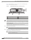
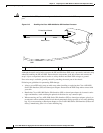
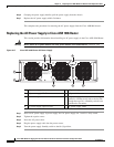
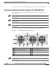
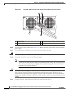
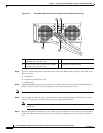
Figure 8-17 Cisco ASR 1006 Router AC Power Supply
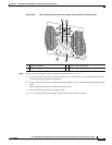
Step 1 Insert an AC power supply in power supply slot 0 or power supply slot 1 until it is fully seated.
Step 2 Tighten the captive screws.
Step 3 Insert the AC power cable.
Step 4 Plug the power supply cable into the power source.
Step 5 Turn the power supply Standby switch to the On (I) position.
1 AC power supply fan 5 AC power supply handle
2 AC power supply DB-25 alarm connector 6 AC power inlet
3 Cable tie wrap tabs 7 AC power supply Standby switch (standby
symbol is a broken circle with a vertical line
through the top of it). A Standby switch is not
considered a disconnect.
4 AC power supply captive screws 8 AC power supply LEDs
280029
OUTPUTINPUT INPUT
FAIL OK OK
ALARMS
60V
1A MAX
100-240V~ 16-7A
50-60HZ
This unit might have more than
one power supply connection.
All connections must be removed
to de-energize the unit.
2 13
4
5
6 7
8