


6-3
Cisco ASR 1000 Series Aggregation Services Routers Hardware Installation and Initial Configuration Guide
OL-13208-03
Chapter 6 Cisco ASR 1002 Router Overview and Installation
Cisco ASR 1002 Router Description
Rear View
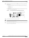
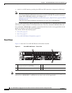
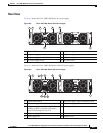
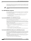
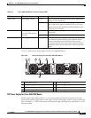
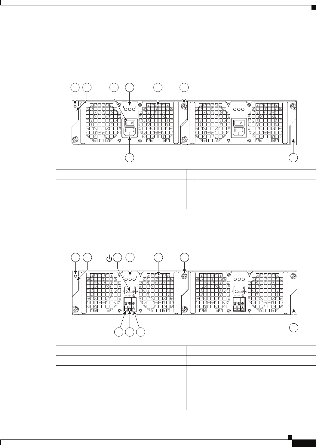
Figure 6-2 shows the Cisco ASR 1002 Router AC power supply.
Figure 6-2 Cisco ASR 1002 Router AC Power Supply
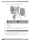
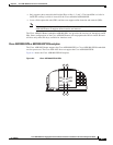
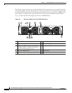
Figure 6-3 shows the Cisco ASR 1002 Router with a DC power supply.
Figure 6-3 Cisco ASR 1002 Router DC Power Supply
1 Chassis ESD socket 5 AC power supply fan
2 AC power supply slot number 0 6 AC power supply captive installation screw
3 AC power supply On (I) /Off (O) switch 7 AC power supply slot number 1
4 AC power supply LEDs 8 AC power inlet
OUTPUTINPUT
FAIL
OK OK
FAN OUTPUTINPUT
FAIL
OK OK
FAN
This unit might have more than
one power supply connection.
All connections must be removed
to de-energize the unit.
This unit might have more than
one power supply connection.
All connections must be removed
to de-energize the unit.
0
1
8 7
280288
41 5 63
2
1 Chassis ESD socket 6 DC power supply captive installation screw
2 DC power supply slot 0 label 7 DC power supply slot 1 label
3 DC power supply switch Standby/On (I)
(standby symbol is a broken circle with a
vertical line through the top of it)
8 Earth ground lead
4 DC power supply LEDs 9 Positive lead
5 Power supply fan 10 Negative lead
280289
OUTPUTINPUT
FAIL
OK OK
FAN
-48V/-60V 16A
This unit might have more than
one power supply connection.
All connections must be removed
to de-energize the unit.
OUTPUTINPUT
FAIL
OK OK
FAN
-48V/-60V 16A
This unit might have more than
one power supply connection.
All connections must be removed
to de-energize the unit.
9 810
4 5 63
0
1
7
1
2