


6-7
Cisco ASR 1000 Series Aggregation Services Routers Hardware Installation and Initial Configuration Guide
OL-13208-03
Chapter 6 Cisco ASR 1002 Router Overview and Installation
Cisco ASR 1002 Router Description
Table 6-2 Cisco ASR 1002 Router AC Power Supply LEDs
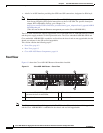
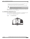
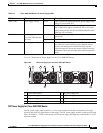
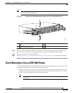
Figure 6-5 shows the AC Power Supply for the Cisco ASR1002 Router.
Figure 6-5 AC Power Supply for the Cisco ASR 1002 Router
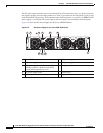
DC Power Supply for Cisco ASR 1002 Router
The DC power supply input connector is a euro-style terminal block and is compliant to all safety
agencies and electrical requirements of the supply. The DC power supply operates within specification
from –40.5VDC to –72VDC continuously once the power supply DC input turn on threshold of –43.5V
has been reached.
LED Label LED Color Description
INPUT OK Power supply activity Green LED is green and signals that the AC power supply input
voltage is greater than 85V.
None If LED is not lighted, the AC input voltage is less than
70V or the power supply is turned off. For an AC input
voltage between 70V and 85V the INPUT OK LED can be
either on, off, or flashing
FAN OK Power supply fan activity
A bi-color LED indicates
fan status.
Green The LED is illuminated green when all fans are
operational.
Red The LED is illuminated red when a fan failure is detected.
OUTPUT FAIL Power supply activity Red LED is red. It is off to signal that the DC output voltages
are within the normal operating range. Output voltage
between the minimum and maximum limits will not
create an output fail alarm and output voltages below the
minimum or above the maximum will create an output fail
alarm.
OUTPUTINPUT
FAIL
OK OK
FAN OUTPUTINPUT
FAIL
OK OK
FAN
This unit might have more than
one power supply connection.
All connections must be removed
to de-energize the unit.
This unit might have more than
one power supply connection.
All connections must be removed
to de-energize the unit.
0
1
8 7
280288
41 5 63
2
1 Chassis ESD socket 5 AC power supply fan
2 AC power supply slot number 0 6 AC power supply captive installation screw
3 AC power supply On (I) /Off (O) switch 7 AC power supply slot number 1
4 AC power supply LEDs 8 AC power supply inlet