


8-39
Cisco ASR 1000 Series Aggregation Services Routers Hardware Installation and Initial Configuration Guide
OL-13208-03
Chapter 8 Replacing Cisco ASR 1000 Series Routers Field-Replaceable Units
Removing and Replacing a DC Power Supply in Cisco ASR 1004 Router
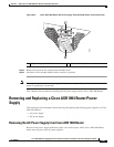
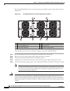
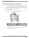
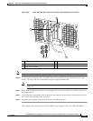
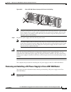
Figure 8-28 Cisco ASR 1004 Router DC Power Supply Terminal Block Ground Cables
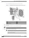
Note Secure the wires coming in from the terminal block so that they cannot be disturbed by casual contact.
Step 10 Use tie wraps to secure the wires, so that the wires are not pulled from the terminal block by casual
contact. Tie-wrap studs are located below the power supply terminal block.
Note The ground wire must contain a loop when securing it to the tie-wrap tab to prevent it from being
pulled out.
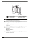
Step 11 Replace the terminal block plastic cover and tighten the screws. The plastic cover slides in easily over
the terminal block.
Step 12 If you taped the circuit breaker, then remove the tape from the circuit-breaker switch handle and move
the circuit-breaker handle to the on
position.
Step 13 Switch the power supply circuit breaker switch to the On (|) position.
This completes the procedure for connecting the DC power supply in the Cisco ASR 1004 Router.
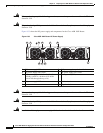
1 Ground stud and wire 4 Flat washer
2 Ground lug nut 5 Kepnut screw
3 Earth ground symbol
280187
2
5 4 3
1