


2-5
Cisco ASR 1000 Series Aggregation Services Routers Hardware Installation and Initial Configuration Guide
OL-13208-03
Chapter 2 Cisco ASR 1000 Series Routers Components
Cisco ASR 1000 Series Route Processor
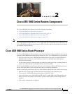
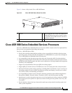
How the Cisco ASR1000-RP1 Alarm LEDs Work
The Cisco ASR1000-RP1 faceplate displays the CRIT, MAJ, and MIN alarm indicator LEDs. A female
DB-25 connector on the power supply faceplate enables you to attach an external alarm monitoring
facility to the router. See
Cisco ASR 1006 Router DB-25 Pinout Assignments for Alarm Relays, page
A-4.
The alarm signals sent to this DB-25 connector are identical in function to those sent to the system LEDs
on the Cisco ASR1000-RP1. Each alarm consists of three contact pins that are switched when an alarm
becomes active which causes a corresponding contact closure between the DB-25 connector pins.
Thus, a critical, major, or minor alarm condition detected in the router can trigger a simultaneous fault
indication in some of the following ways:
• System alarm LEDs—The three system alarm LEDs on the Cisco ASR1000-RP1 faceplate
constitute the standard method of alarm notification in the router. These LEDs indicate router status
at all times, but you must directly observe these LEDs to become aware of a router alarm condition.
• External alarm monitoring facility—By equipping your router with a telco-style external alarm
monitoring facility, you can provide a more physical indication of router status. A visual alarm,
however, can be reset only by resolving the problem that caused the alarm condition.
For example, the same alarm signal that illuminates one of the three system alarm LEDs on the Cisco
ASR1000-RP1 faceplate for a critical, major, or minor alarm condition is also sent to the DB-25
connector by means of an associated alarm relay in the Cisco ASR1000-RP1.
An external alarm monitoring facility uses this signal to activate a visible alarm (such as a flashing
light) or an audible alarm that immediately alerts site personnel to the existence of a router alarm
condition.
An external audible alarm can be reset by clearing the condition that caused the alarm or by pressing the
Audible Cutoff (ACO) button on the Cisco ASR1000-RP1. An audible alarm can be sounded to
immediately alert you of an alarm condition in the router. An audible alarm generated by the system
continues to sound until you either clear the alarm condition itself or press the ACO button to silence the
alarm. Pressing this button does not resolve the alarm condition.
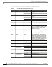
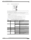
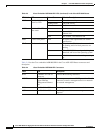
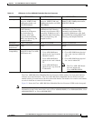
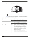
Table 2-2 lists the Cisco ASR 1000 Series Route Processors connectors and description.
Table 2-2 Cisco ASR 1000 Series Route Processor Connectors
Label Type Description
ACO Audible Cutoff button When you press this button, an interrupt is
generated informing software that the audible alarm
relays will be disabled. This interrupt generates to
both processors.
0 USB0 interface Side-by-side USB connector used with memory
sticks or smart cards for secure key distribution
1 USB1 interface Side-by-side USB connector used with memory
sticks or smart cards for secure key distribution
BITS RJ-45 connector Indicates BITS timing reference.
MGMT
ETHERNET
One RJ-45 jack for
copper Ethernet
Management Port
The route processor has an ENET port with a RJ-45
connector to attach a management device or
network for network management.