


CHAPTER
4-1
Cisco ASR 1000 Series Aggregation Services Routers Hardware Installation and Initial Configuration Guide
OL-13208-03
4
Cisco ASR 1006 Router Overview and Installation
This chapter describes the Cisco ASR 1006 Router and provides the procedures for installing the
Cisco
ASR 1006 Router on an equipment shelf or tabletop or in equipment racks. It also describes how
to connect interface and power cables.
This chapter contains the following sections:
• Cisco ASR 1006 Router Description, page 4-1
• General Rack Installation Guidelines, page 4-4
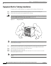
• Guidelines for an Equipment Shelf or Tabletop Installation, page 4-5
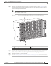
• Equipment Shelf or Tabletop Installation, page 4-6
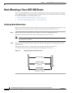
• Rack-Mounting a Cisco ASR 1006 Router, page 4-8
• Attaching the Cable-Management Bracket, page 4-16
• Attaching a Chassis Ground Connection, page 4-17
• Connecting Power to Cisco ASR 1006 Router, page 4-21
• Connecting a Terminal to the Cisco ASR 1000 Series RP1 Console Port, page 4-27
• Connecting System Cables, page 4-29
Cisco ASR 1006 Router Description
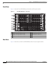
The Cisco ASR 1006 Router supports full-width card modules. It is designed with a single midplane with
connectors on one interface midplane. The Cisco ASR 1006 Router supports:
• Three Cisco ASR 1000 Series SPA Interface Processor (SIP)
• Twelve SPA slots
• Two Cisco ASR 1000 Series Embedded Services Processor (Cisco ASR1000-ESP10 or Cisco
ASR1000-ESP20)
• Two Cisco ASR 1000 Series Route Processor 1 (RP1)
• Dual (redundant) AC and DC power supplies
This section contains the following topics:
• Front View, page 4-2
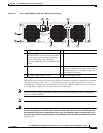
• Rear View, page 4-2