


6-32
Cisco ASR 1000 Series Aggregation Services Routers Hardware Installation and Initial Configuration Guide
OL-13208-03
Chapter 6 Cisco ASR 1002 Router Overview and Installation
Connecting Power to Cisco ASR 1002 Router
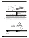
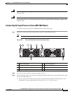
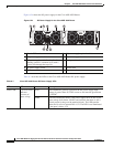
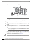
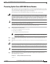
Figure 6-24 shows the DC power supply for the Cisco ASR 1002 Router.
Figure 6-24 DC Power Supply for the Cisco ASR 1002 Router
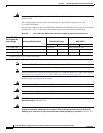
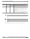
Table 6-7 describes the LEDs on the Cisco ASR 1002 Router DC power supply.
Table 6-7 Cisco ASR 1002 Router DC Power Supply LEDs
1 Chassis ESD socket 6 DC power supply captive installation screw
2 DC power supply slot 0 label 7 DC power supply slot 1 label
3 DC power supply switch Standby/On (I)
(standby symbol is a broken circle with a
vertical line through the top of it)
8 Earth ground lead
4 DC power supply LEDs 9 Positive lead
5 Fan 10 Negative lead
280289
OUTPUTINPUT
FAIL
OK OK
FAN
-48V/-60V 16A
This unit might have more than
one power supply connection.
All connections must be removed
to de-energize the unit.
OUTPUTINPUT
FAIL
OK OK
FAN
-48V/-60V 16A
This unit might have more than
one power supply connection.
All connections must be removed
to de-energize the unit.
9 810
4 5 63
0
1
7
1
2
LED Label LED Color Description
INPUT OK A bi-color LED
indicates
presence of
input voltage
Green LED illuminates green to signal that the DC power supply input
voltage is greater than 43.5VDC at turn-on and remains green down
to 39VDC.
Amber The LED illuminates amber if the power supply turns off due to low
input voltage (falls below 39VDC) and indicates that there is still a
hazard present (voltage on the terminal block). The LED remains
amber and is active to around 20V +/-5V. The LED is not illuminated
if the input is below 15V.