


8-25
Cisco ASR 1000 Series Aggregation Services Routers Hardware Installation and Initial Configuration Guide
OL-13208-03
Chapter 8 Replacing Cisco ASR 1000 Series Routers Field-Replaceable Units
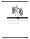
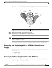
Removing and Replacing a Cisco ASR 1006 Router Power Supply
This completes the procedure for installing the AC power supply in the Cisco ASR 1006 Router.
Removing and Replacing a DC Power Supply in Cisco ASR 1006 Router
This section provides information about removing and installing a DC power supply in the Cisco
ASR
1006 Router.
Warning
When you install the unit, the ground connection must always be made first and disconnected last.
Statement 1046
Warning
Before performing any of the following procedures, ensure that power is removed from the DC circuit.
Statement 1003
Warning
Only trained and qualified personnel should be allowed to install, replace, or service this equipment.
Statement 1030
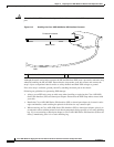
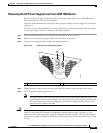
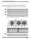
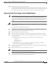
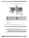
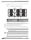
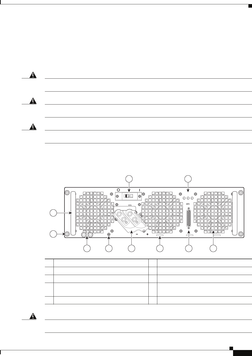
Figure 8-18 shows the DC power supply and components for the Cisco ASR 1006 Router.
Figure 8-18 Cisco ASR 1006 Router DC Power Supply
Warning
Before performing any of the following procedures, ensure that power is removed from the DC circuit.
Statement 1003
1 Fan 6 DC power supply ground studs
2 DB-25 terminal alarm connector 7 DC power supply captive screw
3 Tie-wrap tab 8 DC power supply handle
4 DC power supply terminal block and plastic
cover
9 On/Off (|/O) circuit breaker switch
5 Earth ground symbol 10 Power supply LEDs:
OFF
280023
OUTPUTINPUT INPUT
FAIL OK OK
ALARMS
60V
1A MAX
This unit might have more than one power supply connection. All connections must be removed to de-energize the unit.
-48/-60V 40A
55
2 145 36
7
8
9 10